
Conveyor system having substantially symmetrical longitudinally running electric conductors

A technology of transmission equipment and electric conductors, applied in the direction of conveyors, conveyor objects, conveyor control devices, etc., can solve difficult problems such as realization, and achieve the effect of small transition resistance

Active Publication Date: 2016-05-25
TGW MECHANICS GMBH
View PDF9 Cites 4 Cited by
  • Summary
  • Abstract
  • Description
  • Claims
  • Application Information

AI Technical Summary

Problems solved by technology

[0004] The disadvantage of this arrangement is that the motorized roller can only be mounted at a specific position, namely the position where the conductor track is guided onto the surface of the side jaws
[0005] A further disadvantage is that the curved course of the conveyor belt, the ascent of the conveyor belt and the helical course (curved course of the ascent) of the conveyor belt can only be realized with difficulty by means of the system used in EP0300128A1

Method used


Image

  • Conveyor system having substantially symmetrical longitudinally running electric conductors
  • Conveyor system having substantially symmetrical longitudinally running electric conductors
  • Conveyor system having substantially symmetrical longitudinally running electric conductors

Examples


Embodiment Construction

[0032] At the outset, it should be stated that identical parts in the different embodiments described are provided with the same reference signs or the same part designations, wherein the disclosure contained in the entire description can be transferred to The name of the component. Positional expressions selected in the description (such as above, below, side, etc.) relate to the figures that can be explained and shown directly and, in the event of a position change, are transferred to the new position according to the meaning. Furthermore, individual features or combinations of features originating from different exemplary embodiments shown or described can also represent independent, inventive or inventive solutions.

[0033] A general statement for a numerical range in an objective statement is to be understood as starting from and encompassing any and all subranges, e.g. the expressions 1 to 10 are to be read such that the whole subrange starts from the lower limit 1 and ...


PUM


Abstract

The invention relates to a conveyor system (1), comprising two frame profiles (2, 3) which run such that they are spaced apart from one another, a plurality of motorized conveyor rollers (4) which are arranged in between, an insulator (19) which runs along the at least one frame profile (2) with a plurality of receptacles which are open on the longitudinal side, and a plurality of electric conductors (20) which are arranged in the insulator (19) and are connected electrically to drive electronics of the conveyor rollers (4), wherein in each case one electric conductor (20) is mounted in in each case one receptacle. The form factor f of an electric conductor (20), which is defined as a quotient of the circumference of a circle which is equivalent in area to the cross section of the electric conductor (20) and of the circumference of said cross section of the electric conductor (20), is selected here in the range from f = 0.88 to f = 1.00.

Description

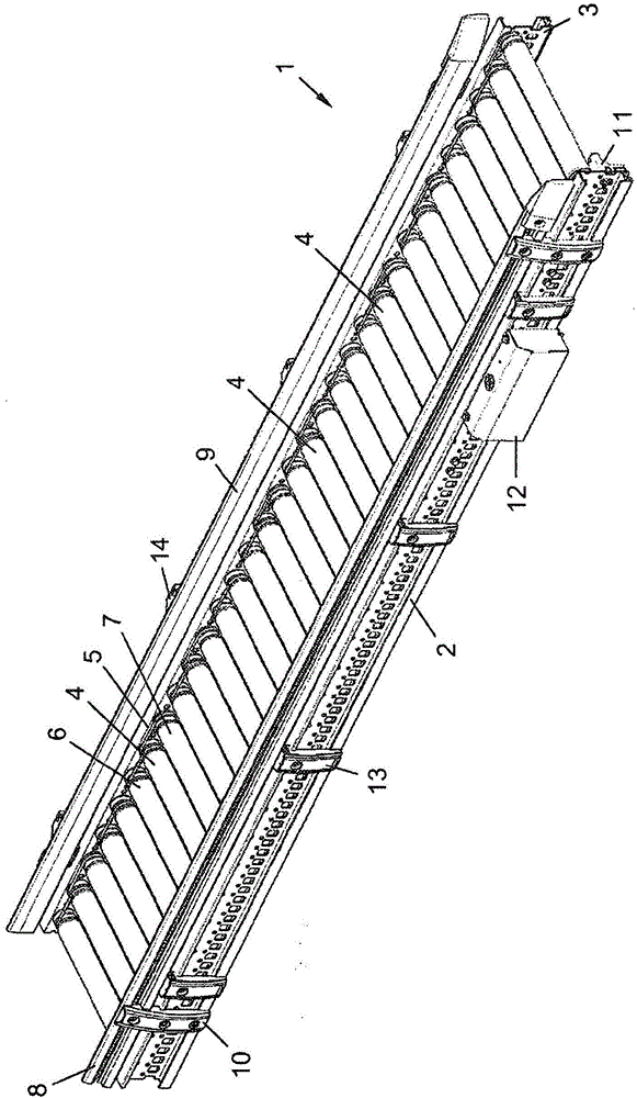
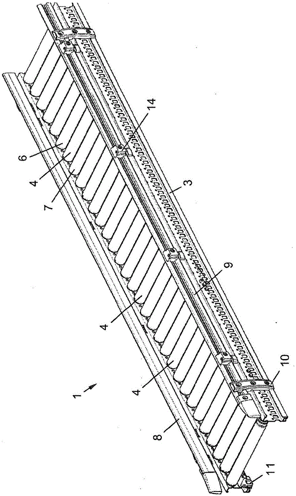
technical field [0001] The invention relates to a conveying device comprising: two frame profiles extending at a distance from each other; a plurality of motorized conveying rollers arranged between them; an insulator extending along at least one frame profile, the insulator having a plurality of Receptacles for electrical conductors of the mouth; and a plurality of electrical conductors arranged in the insulator, which are electrically connected to the drive electronics of the conveying roller, wherein one electrical conductor is placed in each receptacle. Background technique [0002] Such transfer devices are known in principle. In this case, the electrical conductors form a contactable power bus and / or data bus in order to transfer electrical energy and / or data signals between the power supply and the control device for the motorized roller. [0003] For example, EP 0 300 128 A1 discloses a roller conveyor belt for this purpose, in which rectangular conductor tracks are...

Claims


Application Information

Patent Timeline
Patent Type & Authority Applications(China)
IPC IPC(8): B65G43/10B65G13/11
CPCB65G13/06B65G13/11B65G23/08H02G5/04B65G43/10B65G13/02
Inventor J·赖施尔
Owner TGW MECHANICS GMBH
Learn More