Super-resolution optical imaging method based on laser-induced transient aperture probe

A small hole probe, laser-induced technology, applied in the field of super-resolution optical imaging, can solve the problem of sample damage, achieve the effect of low cost, remarkable imaging effect and simple operation

Inactive Publication Date: 2016-05-25
SHANGHAI INST OF OPTICS & FINE MECHANICS CHINESE ACAD OF SCI
View PDF4 Cites 6 Cited by
  • Summary
  • Abstract
  • Description
  • Claims
  • Application Information

AI Technical Summary

Problems solved by technology

However, too short a wavelength will cause damage to the sample, and

Method used


Image

  • Super-resolution optical imaging method based on laser-induced transient aperture probe
  • Super-resolution optical imaging method based on laser-induced transient aperture probe
  • Super-resolution optical imaging method based on laser-induced transient aperture probe

Examples


Embodiment 1

[0035] A super-resolution optical imaging method based on a laser-induced transient pinhole probe, the steps of which include:

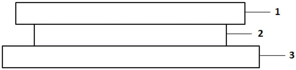
[0036] a) Coating a layer of nonlinear material film 2 on the cover glass 1 by magnetron sputtering;

[0037] b) The above-mentioned cover glass 1 that has been coated with a thin film is closely attached to the surface of the sample 3 to be tested, and the side coated with the thin film is next to the sample;

[0038] c) Scanning and imaging the sample 3 to be tested in a scanning microscope system.

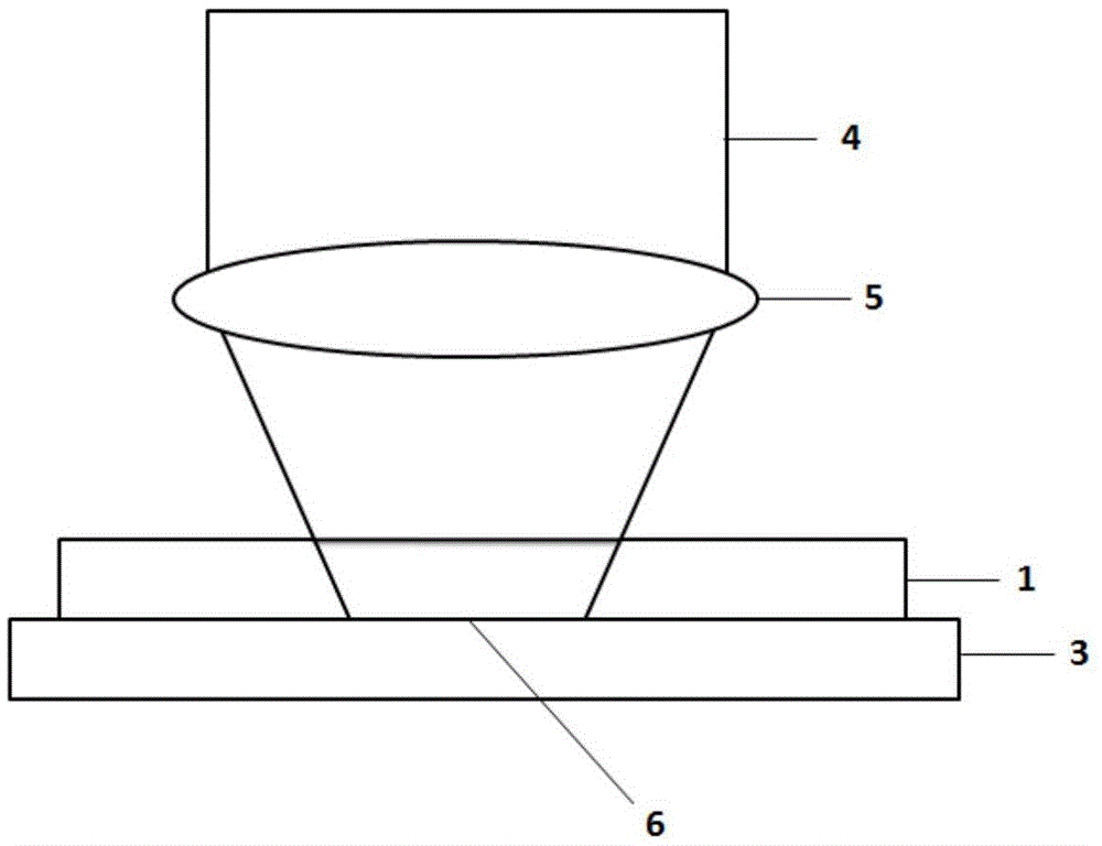
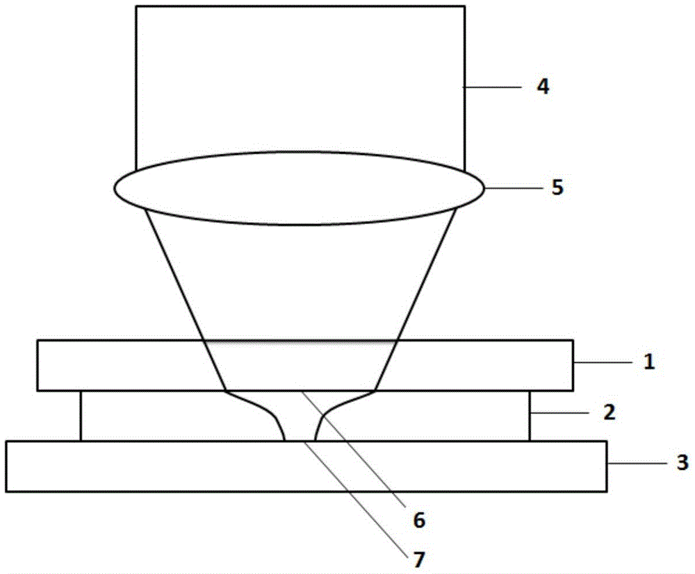
[0039] The cover glass 1 is coated with a nonlinear film 2 and placed on the surface of the sample 3 to be tested, such as figure 1 As shown, the Sb nonlinear thin film material 2 is used, with a thickness of 50 nm, coated on the surface of the cover glass 1, and the coated surface is placed close to the surface of the sample 3 to be tested. When the cover glass 1 is not added with a nonlinear film, its principle is as follows figure 2 As shown, af...

Embodiment 2

[0044] A super-resolution optical imaging method based on a laser-induced transient pinhole probe, the steps of which include:

[0045] a) Coating a non-linear material film 2 on the sample 3 to be tested by magnetron sputtering;

[0046] b) Scanning and imaging the sample 3 to be tested in a scanning microscope system.

[0047] Directly plate the Sb nonlinear thin film 2 on the surface of the sample 3 to be tested, such as Figure 5As shown, just like the sample to be tested in the scanning electron microscope system needs to be coated with a layer of carbon film or gold film on its surface to enhance its conductivity and remove the charge effect. In the scanning microscope system, the Sb nonlinear film 2 can be directly plated on the surface of the sample 3 to be tested, and its thickness is selected as 50nm as in Figure 1, and the same film thickness can be ignored in the test. When the focused laser spot 6 passes through the Sb nonlinear film 2, based on the nonlinear sa...


PUM

PropertyMeasurementUnit
Thicknessaaaaaaaaaa

Abstract

The invention provides a super-resolution optical imaging method based on a laser-induced transient aperture probe. The super-resolution optical imaging method comprises the steps: plating a layer of non-linear material film by means of a magnetron sputtering method; and performing scanning imaging and other steps on a sample in a scanning microscope system, wherein when a laser beam penetrates the non-linear material, based on the non-linear characteristic of the material, the central area of the optical spot section of the non-linear material and the edge area of the non-linear material are different in the transmittance so that the transmittance at the middle part is higher than the transmittance at two edges, so that the limited diameter penetrating the light spot is narrowed and a transient aperture probe is produced in the non-linear material through induction; in the scanning microscope system, the smaller the focused laser beam is, the higher the resolution is; and the transient aperture generated through laser induction can be used to realize a light sport which is less than the laser diffraction limit so as to realize super-resolution optical imaging. The super-resolution optical imaging method based on a laser-induced transient aperture probe is simple and practical, has no demand for complicated operation, is suitable for various forms of samples to be measured, and can acquire an optical resolution which is greater than the diffraction limit.

Description

technical field [0001] The invention relates to an optical imaging method, which is a super-resolution optical imaging method based on a laser-induced transient pinhole probe. Background technique [0002] With the continuous development of society and the continuous advancement of science and technology, it has become an urgent need in various fields to realize nanoscale non-destructive imaging with optical methods. However, because there is a limit in the optical system, that is to say, in the optical scanning imaging system, the scanning spot cannot be reduced to an infinitely small value, and there is a minimum value, which we call the "optical diffraction limit". In 1873, the German scientist Abbe (Abbe) derived the diffraction resolution limit for the first time according to the diffraction theory, and later Rayleigh (Rayleigh) summarized Abbe's diffraction theory into a formula: [0003] r ~ 0.61 λ ...

Claims


Application Information

Patent Timeline
IPC IPC(8): G02B27/58
CPCG02B27/58
Inventor 丁晨良魏劲松
Owner SHANGHAI INST OF OPTICS & FINE MECHANICS CHINESE ACAD OF SCI
Why Eureka
Try Eureka