
Engine system having coolant control valve

一种发动机系统、冷却液的技术,应用在冷却剂流量的控制、发动机元件、发动机的冷却等方向,能够解决冷却液控制阀耐久性变差、不利高温冷却液空化、复杂冷却系统结构等问题,达到有利于空化、提高阀耐久性、简单冷却系统结构的效果

Inactive Publication Date: 2016-05-25
HYUNDAI MOTOR CO LTD
View PDF7 Cites 16 Cited by
  • Summary
  • Abstract
  • Description
  • Claims
  • Application Information

AI Technical Summary

Problems solved by technology

[0009] The outlet control method will fail under sudden changes in water temperature, resulting in low temperature control accuracy and poor durability of the coolant control valve
In addition, the inlet control method is not conducive to the cavitation of high-temperature coolant, and requires a complicated cooling system structure

Method used


Image

  • Engine system having coolant control valve
  • Engine system having coolant control valve
  • Engine system having coolant control valve

Examples


Embodiment Construction

[0032] Reference will now be made in detail to various embodiments of the invention, examples of which are illustrated in the accompanying drawings and described below. While the invention will be described in conjunction with exemplary embodiments, it will be understood that present description is not intended to limit the invention to those exemplary embodiments. On the contrary, the invention is intended to cover not only the exemplary embodiments but also various alternatives, modifications, equivalents and other alternatives, modifications, equivalents and others, which may be included within the spirit and scope of the invention as defined by the appended claims. implementation plan.

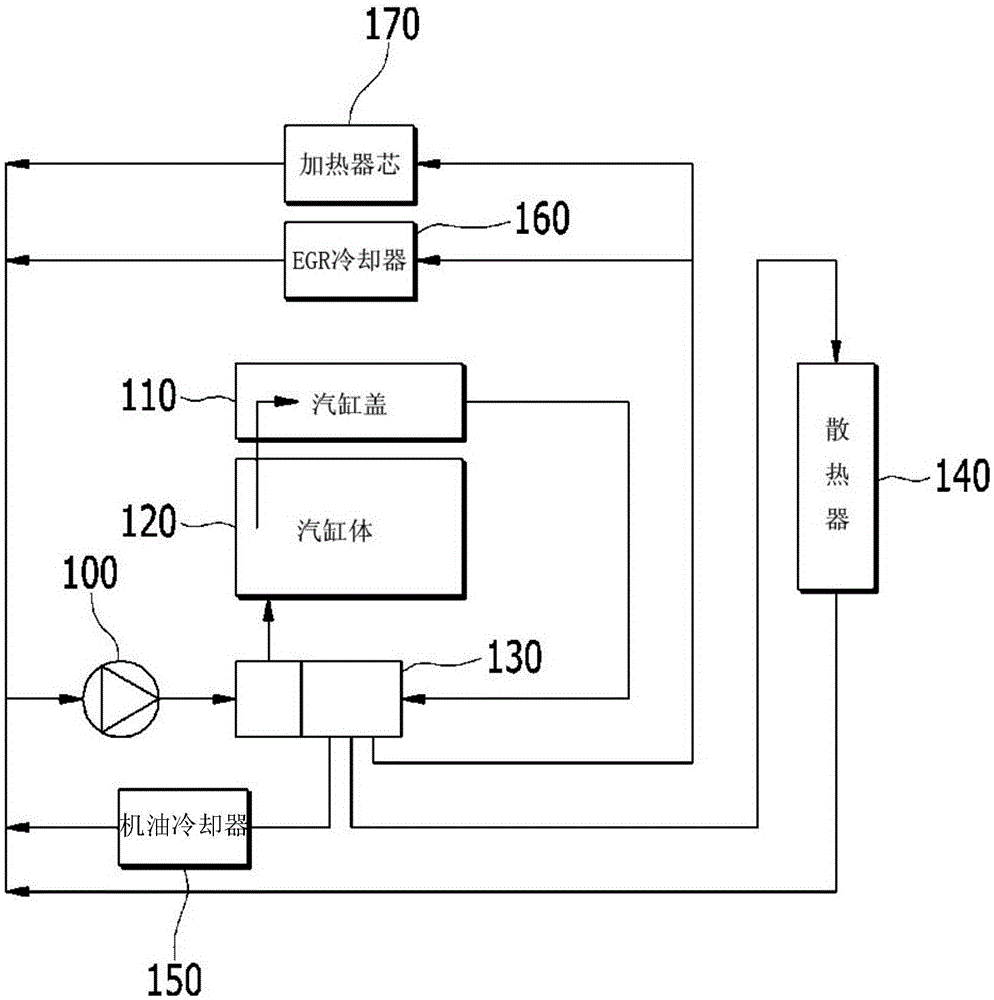
[0033] figure 1 is a flowchart showing the overall flow of coolant in an engine system having a coolant control valve according to various embodiments of the present invention.

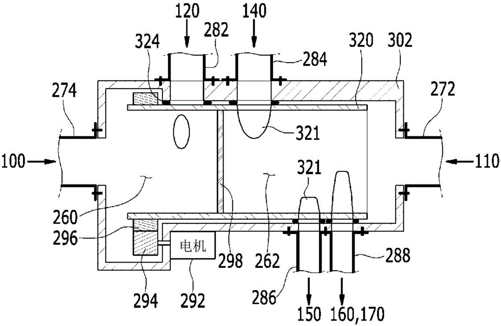
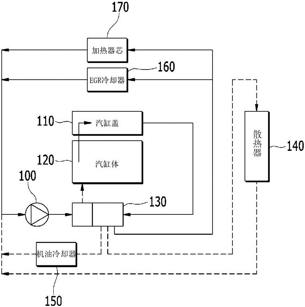
[0034] refer to figure 1 , the engine system includes a cylinder head 110 , a cylinder block 120 , a coola...


PUM


Abstract

An engine system having a coolant control valve may include a cylinder block, a cylinder head, an exhaust gas recirculation (EGR) cooler, a heater core, an oil cooler or a radiator and a coolant control valve. The cylinder block is configured with cylinders; the cylinder head is sitting on top of the cylinder block and comprises exhaust ports and intake ports configured to lead to the cylinders, the Exhaust Gas Recirculation (EGR) cooler, the heater core, the oil cooler, or the radiator through which coolant circulates, and the coolant control valve configured to control a coolant supplied to the cylinder block, a coolant discharged from the cylinder block through the cylinder head, and a coolant supplied to the EGR cooler, the heater core, the oil cooler, or the radiator.

Description

[0001] Cross References to Related Applications [0002] This application claims priority from Korean Patent Application No. 10-2014-0160899 filed on Nov. 18, 2014, the entire contents of which are hereby incorporated by reference for all purposes. technical field [0003] The present invention relates to an engine system having a coolant control valve capable of improving overall cooling efficiency and reducing fuel consumption by controlling both coolant supply to a cylinder block and coolant discharge from a cylinder head. Background technique [0004] The engine produces power by burning fuel to generate torque and expel excess heat. Specifically, as the coolant circulates through the engine, heater, and radiator, the coolant absorbs heat energy and releases heat energy. [0005] The viscosity of the oil becomes higher at low engine coolant temperatures. The use of thicker oil increases friction and fuel consumption, and the exhaust gas temperature gradually increases,...

Claims


Application Information

Patent Timeline
Patent Type & Authority Applications(China)
IPC IPC(8): F01P7/14
CPCF01P7/165F01P2003/027F01P2060/04F01P2060/08F01P2060/16F02M26/23F01P3/02F01P2007/146F02F7/007F02M26/22
Inventor 李孝祚
Owner HYUNDAI MOTOR CO LTD
Learn More