Coal-leveling device and coal-leveling method

A technology of leveling coal and leveling coal holes, which is applied to the field of leveling coal devices on the top of large Kong coal blending bunkers, can solve the problems of increased land occupation and infrastructure costs, increased cost of material distribution equipment, and increased construction and installation costs of the project, so as to save engineering construction and installation The effect of cost, simple structure and high degree of automation

Active Publication Date: 2016-05-25
ACRE COKING & REFRACTORY ENG CONSULTING CORP DALIAN MCC
View PDF6 Cites 5 Cited by
  • Summary
  • Abstract
  • Description
  • Claims
  • Application Information

AI Technical Summary

Problems solved by technology

In addition, the use of double-row material distribution by unloading trucks not only increases the cost of material distribution equipment, but also increases the size of the transfer station before entering the coal bunker, and the corridor must also be double-row, which greatly increases the cost of land occupation and infrastructure; if a reversible mobile belt is used The double-row material distribution of the type conveyor will not only increase the equipment cost, but also need to add a layer of material distribution workshop on the top of the coal bunker; therefore, the double-row material distribution method will increase the area of ​​the material distribution workshop on the top of the coal bunker and increase the construction and installation costs of the project.

Method used


Image

  • Coal-leveling device and coal-leveling method
  • Coal-leveling device and coal-leveling method
  • Coal-leveling device and coal-leveling method

Examples


Embodiment Construction

[0026] The specific embodiments of the present invention will be further described below in conjunction with the accompanying drawings:

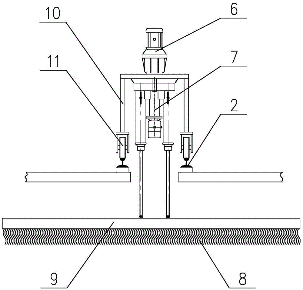
[0027] See Figure 2-Figure 3 , is the structural schematic diagram of the flat coal device of the present invention. The coal leveling device of the present invention includes a coal leveling device trolley arranged on the running track of the trolley on the top of the coal bunker, and the coal leveling device trolley is composed of a trolley frame and a running mechanism fixed on the trolley frame, an electro-hydraulic motor It is composed of single-cylinder double push rod, gear motor and leveling coal mechanism; the trolley of the leveling coal device moves reversibly along the running track of the trolley under the driving of the running mechanism, and the top of the coal bunker between the double-row tracks of the running track of the trolley is provided with a leveling coal hole; the gear motor is located in the small On the frame, t...


PUM


Abstract

The invention relates to a coal-leveling device and a coal-leveling method. The coal-leveling device comprises a coal-leveling device trolley, wherein the coal-leveling device trolley consists of a small frame, a walking mechanism, electro-hydraulic single-cylinder dual push rods, a gear motor and a coal-leveling mechanism, wherein the coal-leveling device trolley can move reversely along a trolley walking track; the top of a coal cabin between dual tracks of the trolley walking track is provided with a coal-leveling hole; the gear motor is arranged on the small frame; the lower part of the gear motor is connected with the coal-leveling mechanism through the electro-hydraulic single-cylinder dual push rods; the coal-leveling mechanism extends into the coal cabin through the coal-leveling hole; the coal-leveling mechanism can be driven to move upwards and downwards by the electro-hydraulic single-cylinder dual push rods; the electro-hydraulic single-cylinder dual push rods and the coal-leveling mechanism can rotate around a horizontal direction under the driving action of the gear motor. According to the coal-leveling device and the coal-leveling method, a mechanical coal-leveling way is adopted, so that the effective volume of a large-sized storage coal cabin is increased, single-row material-distributing wires on the cabin top can be adopted instead of dual-row material-distributing wires, and the distribution equipment cost is saved; the floor space of a material-distributing plant and other facilities on the coal cabin top is reduced, and the engineering building cost is saved.

Description

technical field [0001] The invention relates to a coal leveling device on the top of a large-scale Kong coal blending bunker, in particular to a coal leveling device and a coal leveling method for the top of a Φ18m and Φ21m large storage and blending bunker. Background technique [0002] At present, coal storage sites in coking plants are mainly divided into two categories: coal yards and large coal bunkers. Recently, the newly promulgated "Coking Industry Access Conditions" (revised in 2014) requires that the newly built coal yard must be closed, which greatly increases the cost of the new coal yard. Therefore, large coal bunkers will increasingly become the first choice for new coking plants. [0003] In order to increase the effective volume of the coal bunker, the existing large-scale coal storage and blending bunker in China generally adopts the double-row distribution method. However, due to the natural accumulation of materials, the effective volume of the coal bunke...

Claims


Application Information

Patent Timeline
IPC IPC(8): B65G69/04
Inventor 范程杜光晨李振国
Owner ACRE COKING & REFRACTORY ENG CONSULTING CORP DALIAN MCC
Why Eureka
Try Eureka