
An active-passive mixed upper limb rehabilitation training exoskeleton

A rehabilitation training and exoskeleton technology, applied in passive exercise equipment, sports accessories, elastic resistance devices, etc., can solve problems such as complex structure, waste of gravitational potential energy, waste of drive component output, etc.

Active Publication Date: 2018-03-13
HARBIN INST OF TECH
View PDF5 Cites 1 Cited by
  • Summary
  • Abstract
  • Description
  • Claims
  • Application Information

AI Technical Summary

Problems solved by technology

[0005] Most of the existing exoskeletons are actively driven, but during the movement of the human body, some energy such as gravitational potential energy changes back and forth, but in the process of active drive, the gravitational potential energy is increasing and decreasing. During the process, the driving components all do positive work, which wastes the gravitational potential energy and the output of the driving components
Moreover, the existing upper extremity exoskeleton structure is relatively complex, the energy utilization rate is extremely low, and it is not indirect and aesthetic.
There are some exoskeletons that use the principle of gravity balance, but their structures are more complicated, or they cannot completely achieve gravity balance
For rehabilitation training, in some cases, it is not enough to rely solely on gravity balance. For example, in stroke patients, the upper limbs do not have any movement ability at the beginning, and they need to move the upper limbs passively, and then gradually recover. In the early stage of active movement, Due to the relatively small output force, after balancing the weight of the upper limbs under the action of gravity balance, it is necessary to output the moment to balance the inertial force, so the movement speed will be too slow, which will affect the recovery speed

Method used


Image

  • An active-passive mixed upper limb rehabilitation training exoskeleton
  • An active-passive mixed upper limb rehabilitation training exoskeleton
  • An active-passive mixed upper limb rehabilitation training exoskeleton

Examples


specific Embodiment approach 1

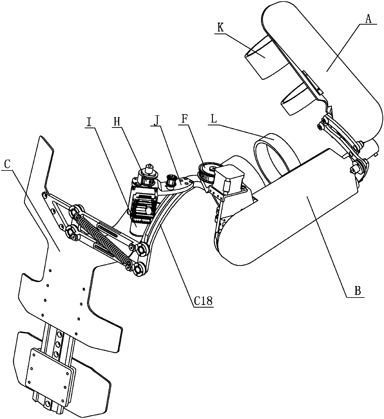
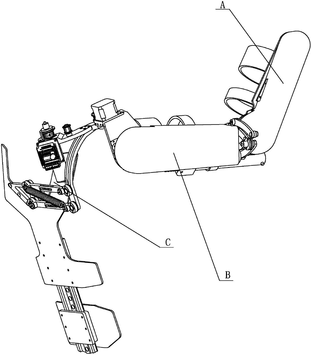
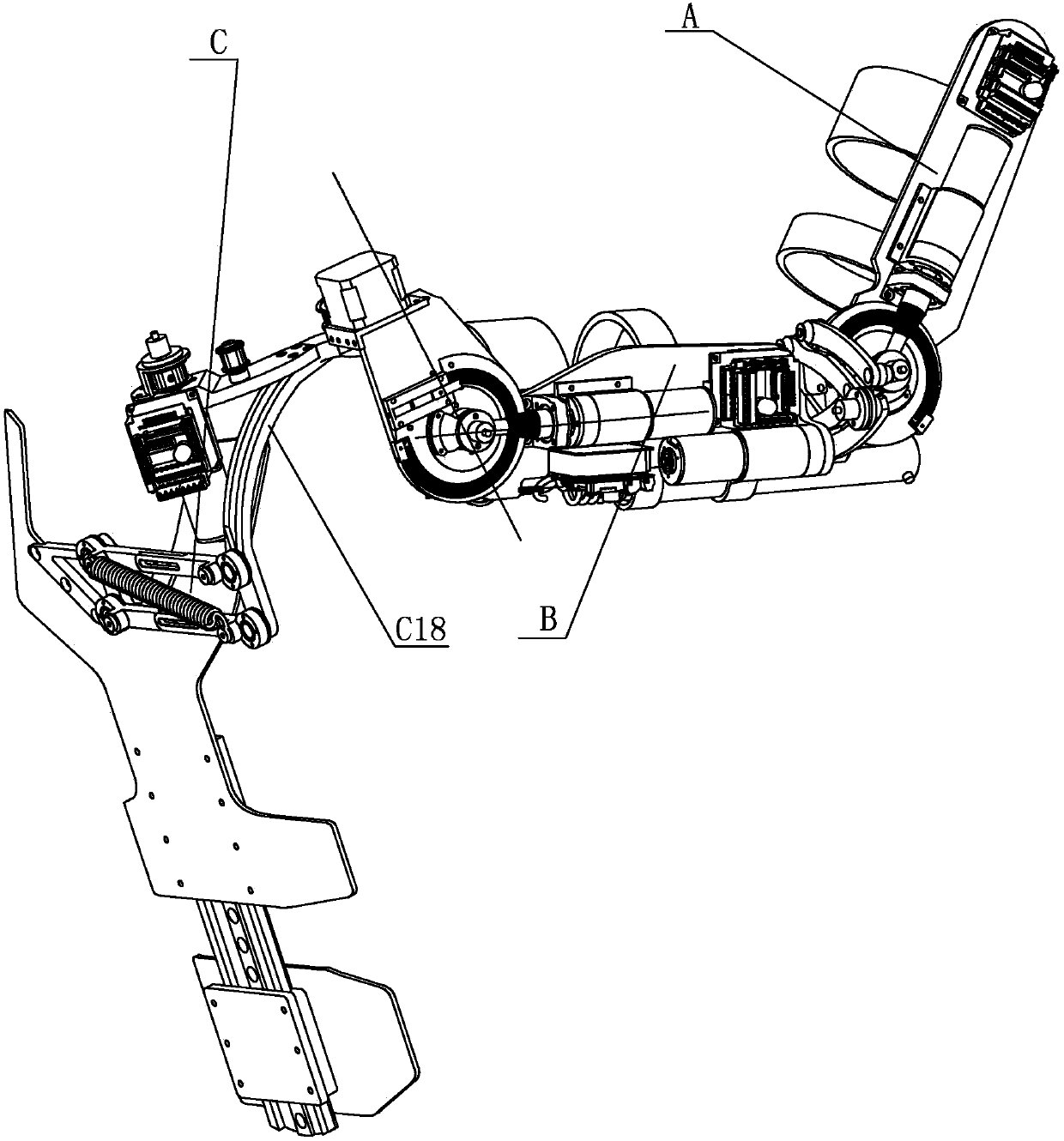
[0029] Specific implementation mode one: combine Figure 1 to Figure 12 Describe this embodiment, this embodiment includes forearm A, big arm B, back C, external rotation shaft D, bearing E, driving pulley F, synchronous belt G, driven pulley H, back drive motor I, The back drive motor seat J, the forearm binding mechanism K, the big arm binding mechanism L, the back drive motor driver P and the back drive motor driver bracket Q,

[0030] See Figure 11, the elbow joint connection seat B45 on the big arm B is fixedly connected with the elbow joint output wheel A4 on the forearm A, one end of the external rotation axis D is hinged in the horizontal frame B1-2 of the shoulder joint skeleton B1, and the external rotation axis D The other end is connected to the inner ring of the bearing E, the shaft end retaining ring M fixes the axial position of the external rotation shaft D, the driving pulley F is fixed on the external rotation shaft D, and one end of the timing belt G is sl...

specific Embodiment approach 2

[0031] Specific implementation mode two: combination Figure 4 with Figure 5 Describe this embodiment, the forearm A of this embodiment includes forearm driver A1, forearm drive motor A2, forearm bearing seat A3, elbow joint output wheel A4, forearm steel wire pretensioning mechanism A5, forearm chute A7, Exoskeleton base plate A8, forearm drive motor base A9, forearm reducer A10, elbow joint input shaft A11, forearm wire rope fixing device A13, elbow joint rotation axis A16 and forearm wire rope A17, and forearm driver A1 is fixedly connected to the exoskeleton On one end surface of the substrate A8, the forearm binding mechanism K is hinged on the other end surface of the exoskeleton substrate A8, the forearm driver A1 is fixedly connected to the exoskeleton substrate A8, and the forearm driver A1 is electrically connected to the forearm drive motor A2 , the forearm drive motor A2 is connected with the forearm reducer A10, the forearm reducer A10 is fixedly connected with ...

specific Embodiment approach 3

[0032] Specific implementation mode three: combination Figure 4 with Figure 5 Describe this embodiment. The difference between this embodiment and the second embodiment is that the forearm A also includes the forearm encoder bracket A6 and the forearm encoder A12, and the forearm encoder bracket A6 is fixed to the elbow joint output wheel A4. The forearm encoder A12 is fixedly connected to the forearm encoder bracket A6. Forearm encoder A12 is used to detect the rotation angle of the elbow joint. The degree of freedom here is the rotational degree of freedom of the elbow joint, which is driven by the forearm drive motor A2. Other components and connections are the same as those in the second embodiment.


PUM


Abstract

The invention discloses an active-passive upper limb rehabilitation training exoskeleton. An elbow joint connecting base on a big arm is fixedly connected with an elbow joint output wheel on a forearm, one end of an outward turning shaft is hinged to a crossarm of a shoulder joint skeleton, and the other end of the outward turning shaft is connected with a bearing inner race; a driving belt wheel is fixedly installed on the outward turning shaft and sleeved with one end of a synchronous belt, a driven belt wheel is sleeved with the other end of the synchronous belt and fixedly installed on an output shaft of a back driving motor, the back driving motor is fixedly connected with a back driving motor base, the back driving motor base is fixedly connected with an arched connecting rod on the back, a back driving motor driver is fixedly connected with the back driving motor base through a back driving motor driver bracket, the back driving motor driver is electrically connected with the back driving motor, a forearm binding mechanism is hinged to an exoskeleton substrate on the forearm, and a big arm binding mechanism is hinged to an exoskeleton upper arm on the big arm. The active-passive upper limb rehabilitation training exoskeleton is applied to rehabilitation medicine, large-scale engineering construction and material handling.

Description

technical field [0001] The invention relates to an exoskeleton robot, in particular to an active-passive hybrid upper limb rehabilitation training exoskeleton. Background technique [0002] Exoskeleton robot is a kind of complex man-machine combination technology, which integrates the knowledge of many scientific fields such as machinery, sensing, control, information, electronic technology and artificial intelligence, and combines human intelligence with the mechanical energy of mechanical power devices. , through human-machine physical contact to transmit force and motion to realize functions such as motion assistance and posture detection, and rely on sensors to realize information interaction with the wearer. [0003] After more than 40 years of development, exoskeletons have become more and more common in many fields. For example, in the military, the assistance of exoskeletons will enhance the endurance of troops in field operations. Exoskeletons provide energy for so...

Claims


Application Information

Patent Timeline
Patent Type & Authority Patents(China)
IPC IPC(8): A63B23/12A61H1/02A63B21/02B25J9/00
CPCA61H1/0274A61H2201/0157A61H2201/1261A61H2201/14A61H2201/1638A61H2201/165A61H2205/06A63B21/02A63B23/1209B25J9/0006
Inventor 朱延河蔡雪风隋东宝
Owner HARBIN INST OF TECH
Learn More