Separate track joint structure

A track joint, separate technology, applied in the field of separate track joint structure, can solve the problems of high production cost, large loss, increased production and sales risks, etc., to reduce production costs, reduce sales risks, and reduce inventory risk effect

Active Publication Date: 2019-01-22
傅文华
View PDF7 Cites 0 Cited by
  • Summary
  • Abstract
  • Description
  • Claims
  • Application Information

AI Technical Summary

Problems solved by technology

[0003] At present, there are two-line track, three-line track and four-line track on the market. For each type of track, the structure of the track light connector is different, so the user must replace the track light with a fixed structure every time. The current track light Both the lamp and the connector are inseparable structures. The sellers sell a whole set of track lights. However, different countries and regions use different tracks. As mentioned above, there are two-wire and three-wire, and there are For four-line, sellers must purchase goods in batches and produce in batches according to the track conditions in different regions. This increases the risk of production and sales to a certain extent. Only one track light, bulb and street light can be used in one place. The structure is inseparable, and the production cost is also high. Once there is a slow-moving situation, the loss will be large

Method used


Image

  • Separate track joint structure
  • Separate track joint structure
  • Separate track joint structure

Examples


Embodiment Construction

[0020] In order to express the present invention more clearly, the present invention will be further described below in conjunction with the accompanying drawings.

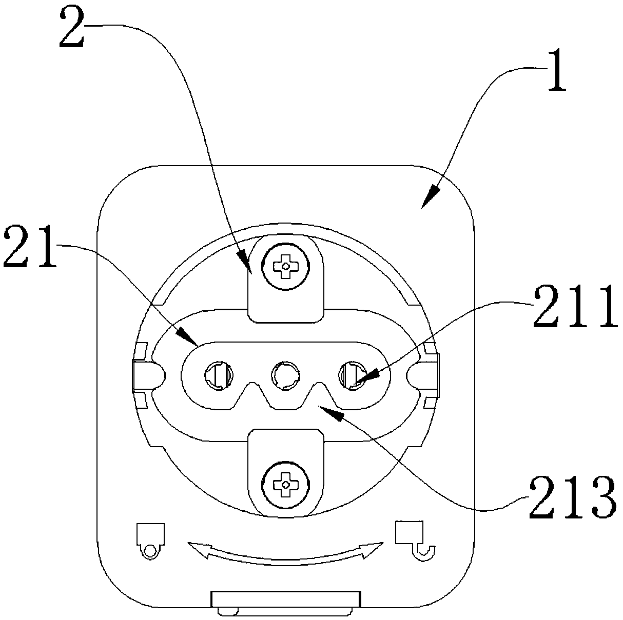
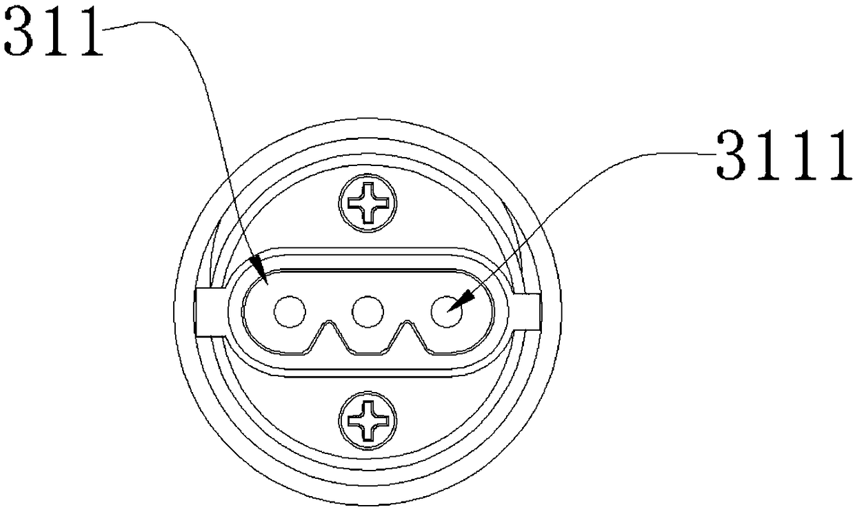
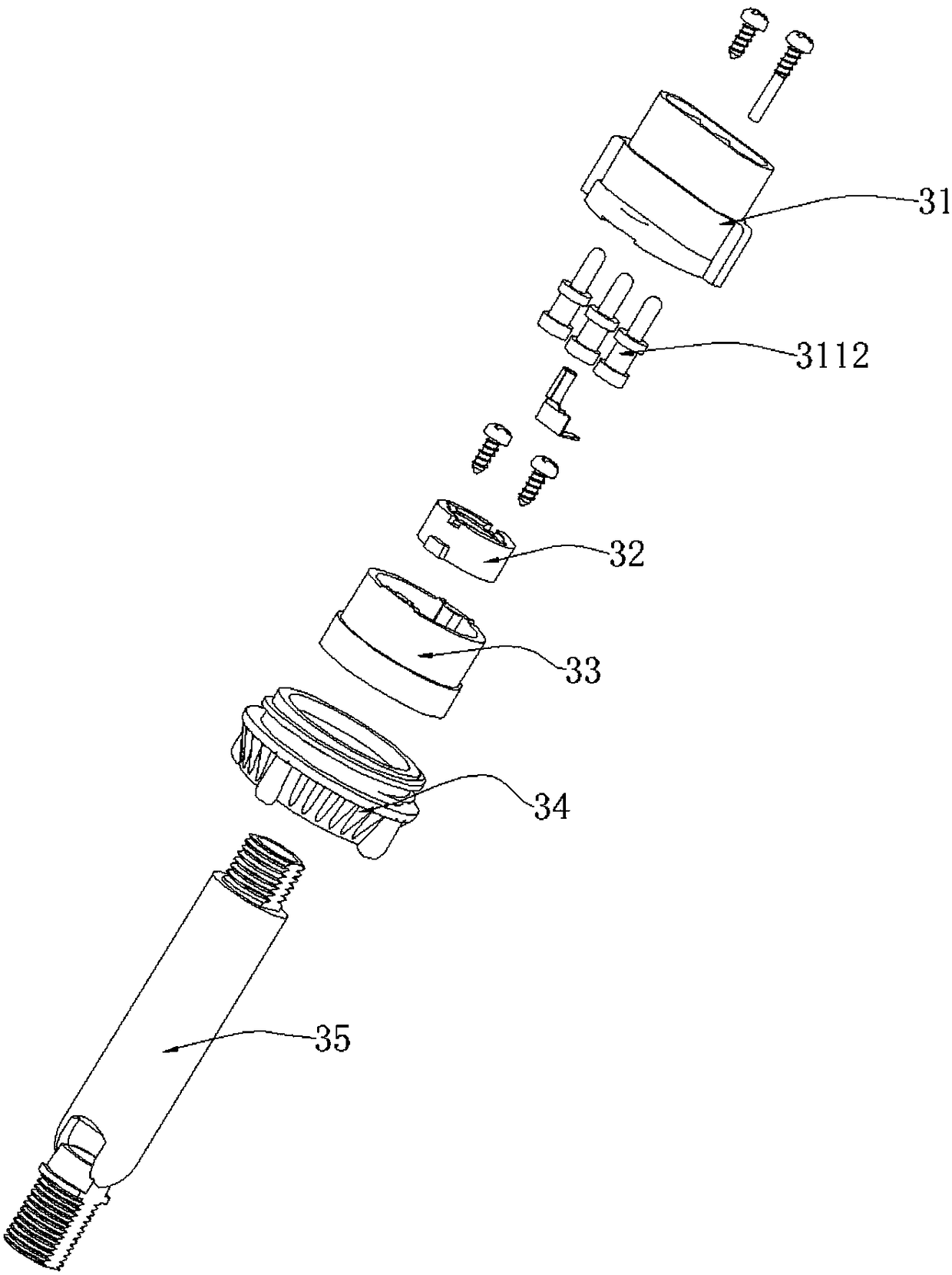
[0021] see Figure 1-Figure 4 , including female connector base 1, female connector 2 and male connector assembly 3, the female connector base 1 is provided with a conductive shrapnel, the conductive shrapnel is connected to the guide rail (not shown) for conduction, and the female connector 2 is fixed on the female connector base 1 by screws Above, the female connector 2 is provided with a first ring 21, and the first ring 21 is provided with a first wire connection hole 211, and the first wire connection hole 211 is connected with the conductive shrapnel, and the first ring 21 is provided with a groove 213, the male connector assembly 3 is also provided with a male connector 31, the male connector 31 is provided with a second circular ring 311 matching the first circular ring 21, and a protrusion 312 is provided...


PUM


Abstract

A separable rail joint structure, comprising a female joint base (1), a female joint (2) and a male joint assembly (3), conductive elastic pieces (14A, 14B) on the female joint base (1) being electrically connected to a guide rail, the female joint (2) having disposed thereon a first ring (21) which is internally provided with first electrical wire connection holes (211) that are connected to the conductive elastic pieces(14A, 14B), the male joint assembly (3) having disposed thereon a male joint (31) which is provided thereon with a second ring (311) that fits to the first ring (21), the second ring (311) having disposed thereon second electrical wire connection holes (3111) that accommodate conductive columns (3112) therein, the conductive columns (3112) being inserted into the first electrical wire connection holes (211) to take power. The rail joint structure uses the connection method in which the male joint (31) fits to the female joint (2), being capable of reducing the production cost, sales risk and inventory risk.

Description

technical field [0001] The invention relates to the technical field of lamps, in particular to a separate track joint structure. Background technique [0002] With people's continuous pursuit of lighting effects, many large shopping malls, concerts or entertainment venues need to use lighting effects to set off the atmosphere. For the convenience and beauty of wiring, track lights are usually used. Track lights are an installable For ceiling or wall lighting fixtures, track lights are installed on the guide rails by setting fixed guide rails on the ceiling or walls, so that the track lights can move on the guide rails. The track light is usually installed on the guide rail through the track joint, so that the track light is driven to slide by the sliding of the track joint on the guide rail. [0003] At present, there are two-line track, three-line track and four-line track on the market. For each type of track, the structure of the track light connector is different, so th...

Claims


Application Information

Patent Timeline
Patent Type & Authority Patents(China)
IPC IPC(8): F21V21/35F21V23/06
CPCF21V21/35F21V23/06H01R13/62
Inventor 傅文华
Owner 傅文华
Why Eureka
Try Eureka