Over-temperature protection circuit and system for LED lamp

An over-temperature protection circuit and LED lamp technology, applied in the field of LED, can solve the problems of inability to monitor real-time LED, fire, LED damage, etc., and achieve the effect of timely over-temperature protection.

Inactive Publication Date: 2016-05-11
上海康耐司信号设备有限公司
View PDF5 Cites 1 Cited by
  • Summary
  • Abstract
  • Description
  • Claims
  • Application Information

AI Technical Summary

Problems solved by technology

At the same time, it is impossible to monitor the LED in real time, which may cause damage to the LED, or even cause a fire

Method used


Image

  • Over-temperature protection circuit and system for LED lamp
  • Over-temperature protection circuit and system for LED lamp
  • Over-temperature protection circuit and system for LED lamp

Examples


Embodiment 1

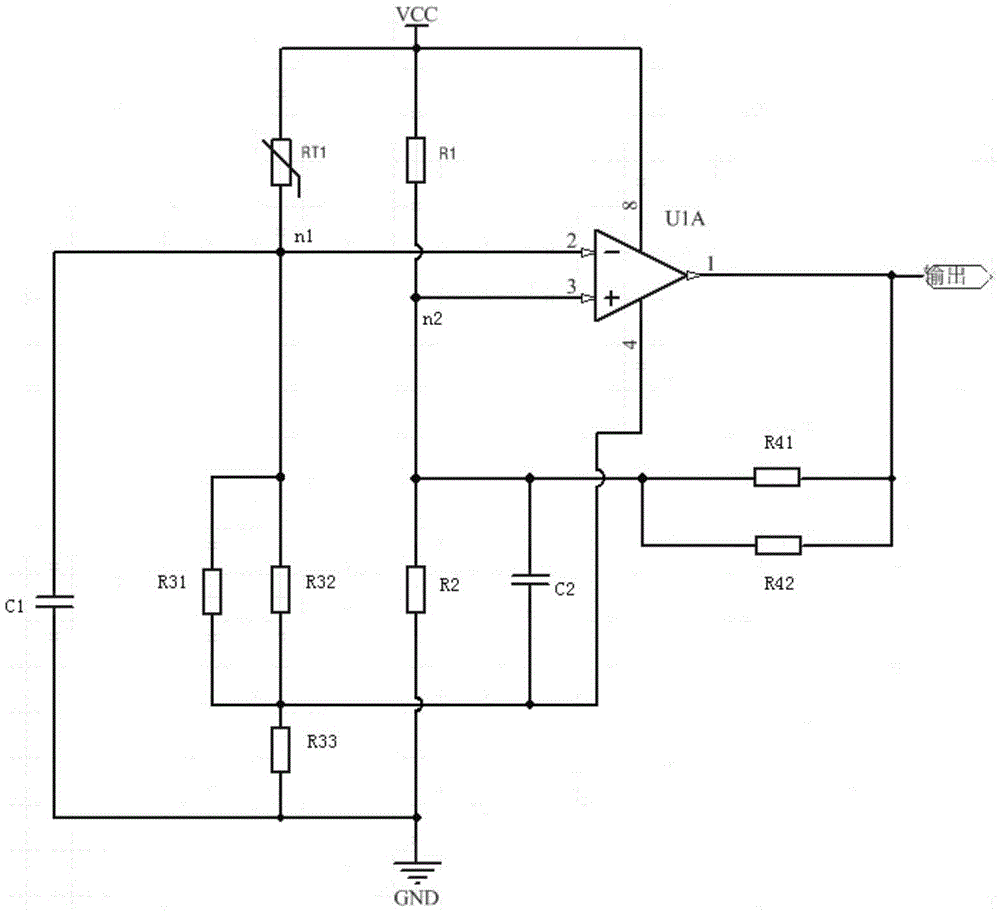
[0033] figure 1 It is the circuit schematic diagram of the LED over-temperature protection circuit according to the embodiment of the present invention, such as figure 1 As shown, this embodiment provides an LED lamp over-temperature protection circuit, in which:

[0034] The first resistor R1 and the second resistor R2 are connected in series, and a first node is arranged between the first resistor R1 and the second resistor R2; the thermistor RT1 connected in series and the third resistor R3 (the third resistor in this embodiment Composed of a circuit composed of resistor R31, resistor R32 and resistor R33, but this is only a preferred situation, other equivalent circuits should also be understood as being included in the present invention), and between the thermistor RT1 and the third resistor A second node n2 is arranged between them; the first comparator U1A has a forward input terminal, a reverse input terminal and an output terminal, and the forward input terminal is c...

Embodiment 2

[0037] Such as figure 2 As shown, this embodiment proposes an LED lamp over-temperature protection system, in which:

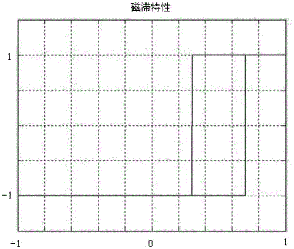
[0038] The temperature sensor 1 is connected with the thermistor with negative temperature characteristics to detect the temperature signal of the LED lamp, and use the temperature signal to change the resistance value of the thermistor; the hysteresis temperature control unit 2 is connected with the temperature sensor 1 for The hysteresis of the temperature signal controls the on-off of the LED lamp; the zero-voltage trigger unit 3 is connected with the hysteresis temperature control unit 2, and generates and outputs a trigger signal when the output voltage of the hysteresis temperature control unit 2 is zero; the alarm unit 4 and the zero-voltage trigger The unit 3 is connected to generate and output an alarm signal for alarm according to the trigger signal.

[0039] Preferably, the zero-voltage trigger unit 4 includes a second comparator, the inverting in...


PUM


Abstract

The invention relates to the field of an LED, and particularly to an over-temperature protection circuit and system for an LED lamp. The input voltage at an inverted input end of a first comparator is changed by a thermistor; meanwhile, the over-temperature protection for the LED lamp is realized by hysteretic characteristics formed by a feedback circuit formed by a fourth resistor that is connected between a first junction point and the output end of the first comparator in series; the invention also provides an over-temperature protection system for the LED lamp; a temperature signal is obtained through a temperature sensor; the input voltage input to a hysteretic temperature control unit is adjusted according to the temperature signal so as to control the operating on-off states of the LED lamp; and meanwhile, when the output voltage of the hysteretic temperature control unit is zero, a trigger signal is generated by a zero voltage trigger unit to trigger an alarm unit to sent out an alarm so as to realize the in-time over-temperature protection for the LED lamp.

Description

technical field [0001] The invention relates to the field of LEDs, in particular to an LED lamp over-temperature protection circuit and system. Background technique [0002] Work lights are mainly used in various large-scale construction operations, accident repairs, emergency rescue and disaster relief and other work site lighting lamps. They are small in size and high in brightness, and use high-efficiency LEDs. Because of the high power and high brightness, the lamp body will become a heat source. When the LED is under high temperature for a long time, it will cause great damage to the LED, seriously affect the life of the LED and cause the light decay of the LED. [0003] The existing temperature protection circuit is to set a threshold. When the temperature is higher than the threshold, the circuit will stop working and the output of the LED will be turned off. When the temperature is lower than the threshold, the drive circuit will be turned on and the LED will be tur...

Claims


Application Information

Patent Timeline
IPC IPC(8): H05B33/08H05B44/00
CPCH05B45/50Y02B20/30
Inventor 韦润芝
Owner 上海康耐司信号设备有限公司
Why Eureka
Try Eureka