
An anti-sluggish tool for reducing friction, reducing drag, saving energy and increasing efficiency

A technology for reducing friction and drag, tools, applied in drilling tools, drilling equipment, earth-moving drilling and other directions, can solve problems such as the impact of the normal operation of the drill bit, the impact of the rock-breaking effect, and the stuck drill, so as to alleviate the phenomenon of stuck drilling and pressure holding, The effect of improving rock breaking efficiency and stable working performance

Inactive Publication Date: 2017-09-01
SOUTHWEST PETROLEUM UNIV
View PDF6 Cites 0 Cited by
  • Summary
  • Abstract
  • Description
  • Claims
  • Application Information

AI Technical Summary

Problems solved by technology

Regardless of whether it is a horizontal well, a vertical well, a branch well or an extended-reach well and other structural wells, during the drilling process, due to the complex formation environment in which the drill bit is located, the reaction force and reverse torque the drill bit receives during operation are also constantly changing, resulting in The rock-breaking effect of the drill bit at the bottom of the hole is affected
At the same time, during the drilling process, due to reasons such as well wall collapse and falling objects, the normal operation of the drill bit will be affected. In severe cases, the phenomenon of drill sticking may even occur, resulting in pressure holding, shortening the service life of the drill bit, and thus affecting the entire drilling operation.

Method used


Image

  • An anti-sluggish tool for reducing friction, reducing drag, saving energy and increasing efficiency
  • An anti-sluggish tool for reducing friction, reducing drag, saving energy and increasing efficiency
  • An anti-sluggish tool for reducing friction, reducing drag, saving energy and increasing efficiency

Examples


Embodiment Construction

[0019] The present invention will be further described below in conjunction with accompanying drawing:

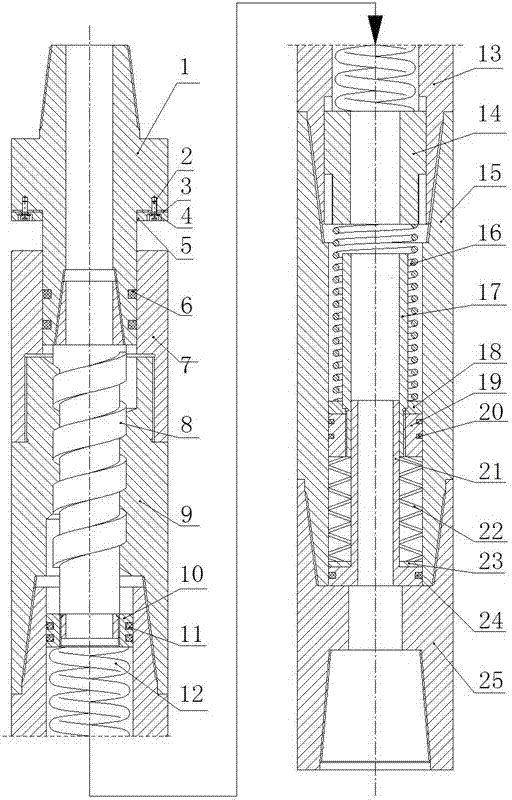
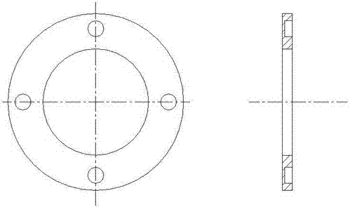
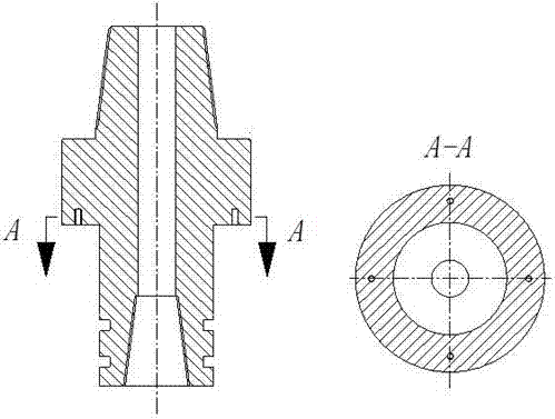
[0020] see figure 1 The anti-sluggish tool for reducing friction, reducing drag, saving energy and increasing efficiency includes an upper joint assembly, a transmission assembly, a vibration-absorbing assembly, and a lower joint 25. The transmission assembly is installed at the front end of the transmission assembly, and the front end of the transmission assembly is connected with the vibration-absorbing assembly; The gasket 3 and the rubber ring 5 are fixedly connected to the upper joint 1, and the rubber ring 5 is used to buffer the impact generated when the short joint 7 moves backwards and contacts the upper joint 1, and at the same time avoid the rear end of the short joint 7 from directly contacting the upper joint 1, Thereby reducing the vibration generated when the tool is working.

[0021] The transmission assembly includes a spiral nipple 8, a spiral outer cyli...


PUM


Abstract

The invention relates to a viscous motion preventing instrument capable of realizing friction reduction, drag reduction, energy saving and synergy. The viscous motion preventing instrument is fixedly installed at the upper part of a drill bit and comprises an upper contact assembly, a drive assembly, a vibration absorption assembly and a lower contact, wherein the drive assembly is installed at the front end of the upper contact assembly and the vibration absorption assembly is connected with the front end of the drive assembly. A screw short piece and a screw outer tube are matched to transmit torque to the drill bit. When the drill bit is stuck, the torque on bit gradually increases and reacts on the viscous motion preventing instrument so that a torsion spring is loaded and distorts, a spline moves forward, a spring and a disc spring are compressed, the torsion spring restores when the spring and disc spring are compressed to limit, the screw outer tube produces reversing rotation through the spline, and the screw outer tube moves rearward relative to the screw short piece. Thus, the torque on bit is decreased and keeps in balance with the torque of the upper instrument again, and the drill bit works normally. The viscous motion preventing instrument capable of realizing friction reduction, drag reduction, energy saving and synergy has the advantages of stable working performance, good vibration absorption effect and good structural performance and transmits drilling pressure and torque through screw drive.

Description

technical field [0001] The invention belongs to the field of petroleum and natural gas drilling engineering, and is an energy-saving and efficiency-enhancing tool, in particular to an anti-sluggish tool for realizing friction reduction, energy-saving and efficiency-enhancing. Background technique [0002] The oil and gas exploration and development process is a process in which the working conditions and environment are constantly changing. With the continuous drilling of the drill bit, the drilling depth becomes deeper and deeper, and the formation characteristics become more and more complex. It's getting more and more complicated. Regardless of whether it is a horizontal well, a vertical well, a branch well or an extended-reach well and other structural wells, during the drilling process, due to the complex formation environment in which the drill bit is located, the reaction force and reverse torque the drill bit receives during operation are also constantly changing, re...

Claims


Application Information

Patent Timeline
Patent Type & Authority Patents(China)
IPC IPC(8): E21B12/00E21B12/04
CPCE21B12/00E21B12/04
Inventor 田家林杨应林袁长福胡书辉蔡旭东杜凡周韬
Owner SOUTHWEST PETROLEUM UNIV
Learn More