


Quick Research
Generate reliable direction feasibility study reports for your R&D in just a few steps.

Technical Q&A
Discover and master advanced knowledge NOW. Basics, ideas, possibilities, all at once.

Find Solutions
As an expert in R&D theories, this can generate solutions to your technical problems instantly.

Evaluate Feasibility
Analyze your overall solution with one click, know your potential R&D risks in advance.

Monitor Landscape
Get weekly tech updates, stay abreast of the latest tech innovations and key insights.
Illumination device and display device
A technology for lighting devices and display surfaces, which is applied to light guides, instruments, light guides, etc. The effect of image quality and uniform brightness
- Summary
- Abstract
- Description
- Claims
- Application Information
AI Technical Summary
Problems solved by technology
Method used
Image


Examples
Embodiment approach 1
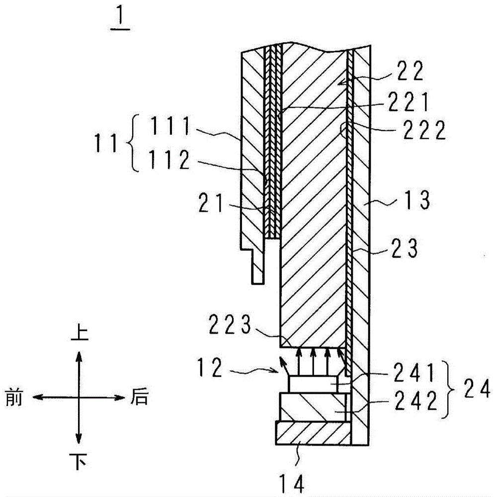
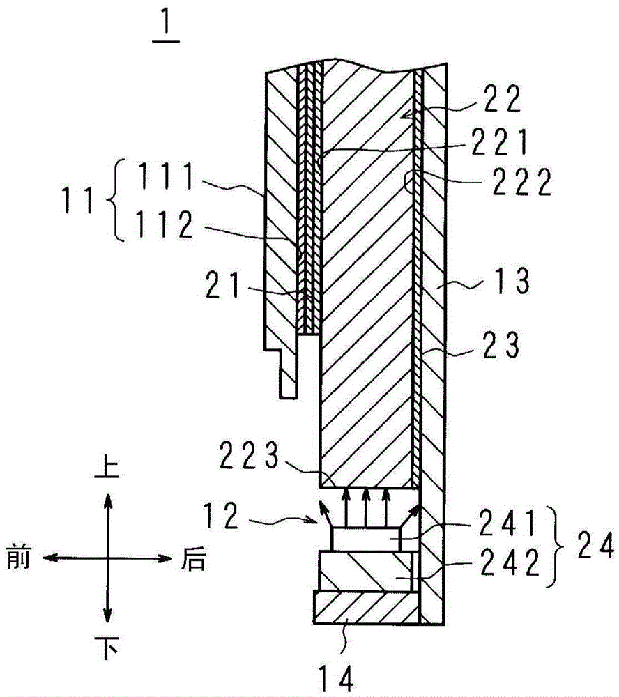
[0044] figure 1 as well as figure 2 It is a vertical cross-sectional view schematically showing the structure of the display device 1 according to Embodiment 1 of the present invention. exist figure 1 as well as figure 2 In the figure, the vicinity of the lower side of the reflective sheet 23 to be described later is shown. And, in figure 1 shows the left or right end of the reflection sheet 23, in figure 2 The center part in the left-right direction of the reflective sheet 23 is shown in .
[0045] image 3 It is a front view schematically showing the positional relationship between the reflection sheet 23 and the light source unit 24 included in the backlight unit 12 which is the lighting device according to Embodiment 1 of the present invention.
[0046] The display device 1 of the present embodiment is configured as, for example, a television receiver, an electronic signboard, or a monitor for a personal computer.
[0047] First, the configuration of the display...
Embodiment approach 2
[0098] Figure 5 It is a front view schematically showing the positional relationship between the reflection sheet 23 and the light source unit 24 included in the backlight unit 12 according to Embodiment 2 of the present invention. Figure 5 with Embodiment 1 image 3 correspond.
[0099] The backlight unit 12 of the present embodiment has substantially the same configuration as the backlight unit 12 of the first embodiment. Hereinafter, differences from Embodiment 1 will be described, and other parts corresponding to Embodiment 1 will be given the same reference numerals and descriptions will be omitted.
[0100] Generally, less important video is displayed on the left and right ends of the display surface 111 of the display panel 11 than in the center of the display surface 111 in the left and right direction of the display panel 11 . Therefore, the user sometimes desires that the display surface 111 be uniformly bright in the range where an important video is displayed ...
Embodiment approach 3
[0106] Image 6 It is a front view schematically showing the positional relationship between the reflection sheet 23 and the light source unit 24 included in the backlight unit 12 according to Embodiment 3 of the present invention. Image 6 with embodiment 2 Figure 5 correspond.
[0107] The backlight unit 12 of the present embodiment has substantially the same configuration as the backlight unit 12 of the second embodiment. Hereinafter, differences from Embodiment 2 will be described, and other parts corresponding to Embodiment 2 will be given the same reference numerals and descriptions will be omitted.
[0108] In Embodiment 2, the protrusions 232, 232 are disposed at positions W / 9 away from the left and right ends of the reflection sheet 23, but in this embodiment, the protrusions 232, 232 are disposed at a distance W / 9 from the reflection sheet 23. The left and right ends of the W / 4 position.
[0109] When such a reflective sheet 23 is used, in terms of surface emiss...
PUM
 Abstract
Description
Claims
Application Information
 - R&D Engineer
- R&D Manager
- IP Professional
- Industry Leading Data Capabilities
- Powerful AI technology
- Patent DNA Extraction
Browse by: Latest US Patents, China's latest patents, Technical Efficacy Thesaurus, Application Domain, Technology Topic, Popular Technical Reports.
© 2024 PatSnap. All rights reserved.Legal|Privacy policy|Modern Slavery Act Transparency Statement|Sitemap|About US| Contact US: help@patsnap.com