A rotating magnetic field device
A technology of rotating magnetic field and equipment, applied in the directions of magnets, permanent magnets, magnetic objects, etc., can solve the problems of insufficiently optimized magnetic field distribution, unfavorable strong magnetic field settings, high motor power, etc., to achieve high effective magnetic field utilization and better magnetic health care effect. The best, the effect of force distribution optimization
- Summary
- Abstract
- Description
- Claims
- Application Information
AI Technical Summary
Problems solved by technology
Method used
Image

Examples
Embodiment 1
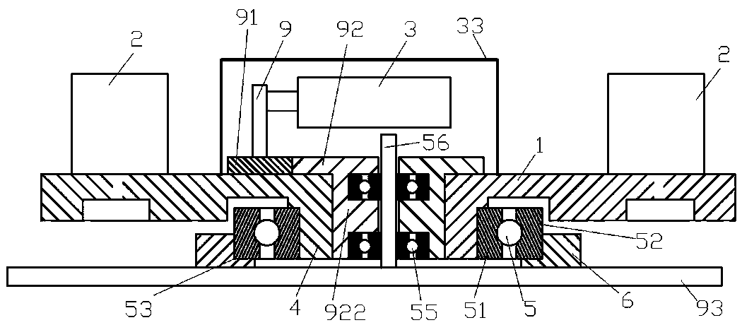
[0027] Example 1, such as figure 1 As shown, a rotating magnetic field device includes a longitudinal drive shaft 9, the longitudinal drive shaft 9 is connected with a motor 3, the upper end of the longitudinal drive shaft 9 is connected with a gear set 91, and the gear set 91 is meshed with a drive gear 92 , the lower part of the driving gear 92 is fixed with a basic rotating disk 1 , and a magnetic assembly 2 is mounted on the basic rotating disk 1 . The gear set 91 can adopt structures such as a single gear or a variable speed gear combination or a gear box. Further, the power of the motor can be reduced, and the high load demand can be met with a low-power motor, and the speed change can also be realized; the basic rotating disk 1 should be placed as flat as possible And it is preferably arranged that the external shape is axisymmetric or centrosymmetric, and the number of magnetic assemblies 2 is preferably an even number, which is arranged around the central area. The ma...
Embodiment 2
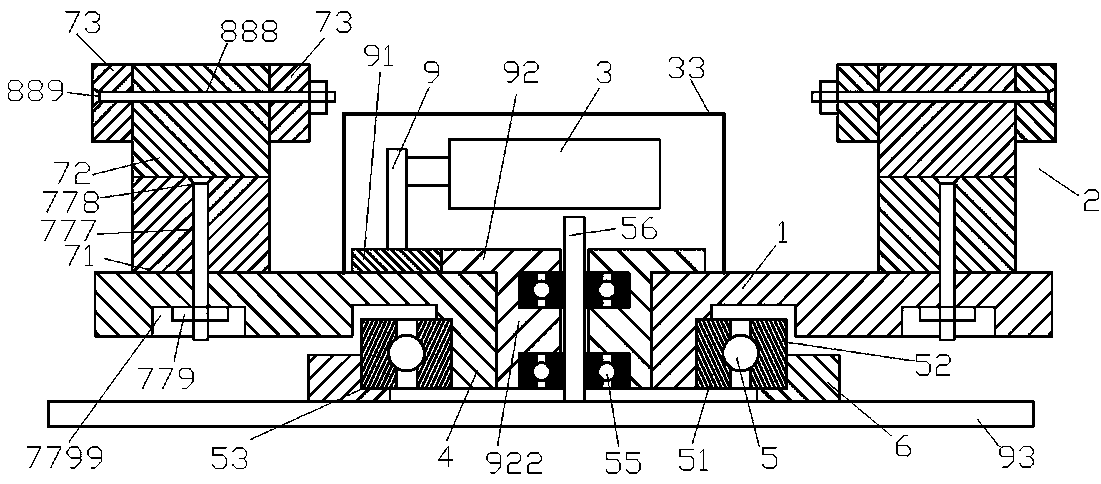
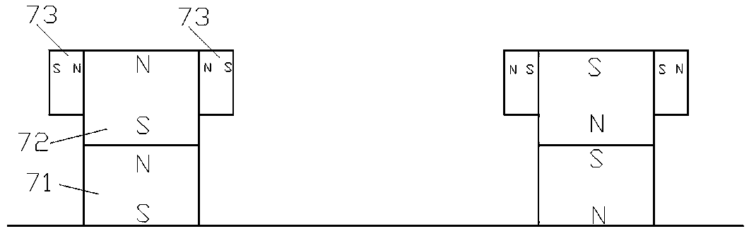
[0031] Example 2, such as figure 2 , 3 As shown, the difference between it and Embodiment 1 is: the design of the magnetic assembly 2. In this embodiment, the first solution, the magnetic assembly 2 includes the base main pole piece 71 installed on the base rotating disk 1, the base main pole piece 71 can be used alone as the magnetic assembly 2 directly, and a cuboid or cube-shaped magnetic pole piece with a relatively large surface magnetic field strength can be used; in the second scheme, the magnetic assembly 2 not only includes the base main magnetic pole piece 71, but also includes the upper main magnetic pole piece 72, The upper main magnetic pole piece 72 is arranged on the top of the base main magnetic pole piece 71, and the upper main magnetic pole piece 72 can also adopt a cuboid or cube-shaped magnetic pole piece with a larger surface magnetic field strength. The upper main magnetic pole piece 72 and the base main magnetic pole piece 71 The size can be set to be ...
Embodiment 3
[0032] Example 3, such as Figure 4 As shown, the difference between it and Embodiment 1 or 2 is that the outer side of the magnetic assembly 2 is covered with a protective cover 8, and the lower part of the protective cover 8 extends to form a cover installation piece 80 for fixed connection with the basic rotating disk 1. The cover installation piece 80 can be installed and fixed with the basic rotating disk 1 through screws, etc. The protective cover 8 is a non-magnetic isolation stainless steel cover, that is, a non-magnetic stainless steel outer cover can be used, which is not only beautiful, but also protects the magnetic pole pieces from being oxidized and prevents ferromagnetic objects from being directly Collision and contact with the magnetic pole piece can also prevent the magnetic assembly 2 from falling off during high-speed operation and cause accidents, further optimize the structure and force distribution, improve various physical properties, and have better mag...
PUM
 Abstract
Description
Claims
Application Information
 - R&D
- Intellectual Property
- Life Sciences
- Materials
- Tech Scout
- Unparalleled Data Quality
- Higher Quality Content
- 60% Fewer Hallucinations
Browse by: Latest US Patents, China's latest patents, Technical Efficacy Thesaurus, Application Domain, Technology Topic, Popular Technical Reports.
© 2025 PatSnap. All rights reserved.Legal|Privacy policy|Modern Slavery Act Transparency Statement|Sitemap|About US| Contact US: help@patsnap.com