
Device and method for realizing swing of rotating shaft of turn table

A technology of rocking motion and rotating table, which is applied in the direction of non-electric variable control, instrument, mechanical vibration control, etc., can solve the problems such as difficult adjustment of frequency and amplitude, unstable start and stop, large volume of rotating table, etc., and achieves simple structure, Rocking start and smoothing, effects that improve rocking precision

Active Publication Date: 2016-05-04
BEIJING INST OF AEROSPACE CONTROL DEVICES
View PDF4 Cites 4 Cited by
  • Summary
  • Abstract
  • Description
  • Claims
  • Application Information

AI Technical Summary

Problems solved by technology

[0002] The swing motion of the rotary table generally has two schemes: the direct drive of the rotating shaft and the use of a reduction mechanism. The direct drive of the rotating shaft has high precision, but usually requires a high-torque motor, which will result in a large volume of the rotary table and high cost; the common use of the reduction mechanism is to use two There are two kinds of transmission devices, one is the mode of the reducer, which has a space error, resulting in low swing accuracy; the other is the cam transmission mode, which is not easy to adjust the frequency and amplitude, and the cam is easy to wear, which is inconvenient to use
In terms of algorithm, it usually adopts timing positioning method, and the timing interval is generally greater than 10 milliseconds. The start and stop of the rotating shaft generally adopts a sinusoidal smoothing method. The main problem is that there are few sampling points. When the frequency is greater than or equal to 10 Hz, the waveform distortion is relatively large. Jerky starts and stops

Method used


Image

  • Device and method for realizing swing of rotating shaft of turn table
  • Device and method for realizing swing of rotating shaft of turn table
  • Device and method for realizing swing of rotating shaft of turn table

Examples


Embodiment Construction

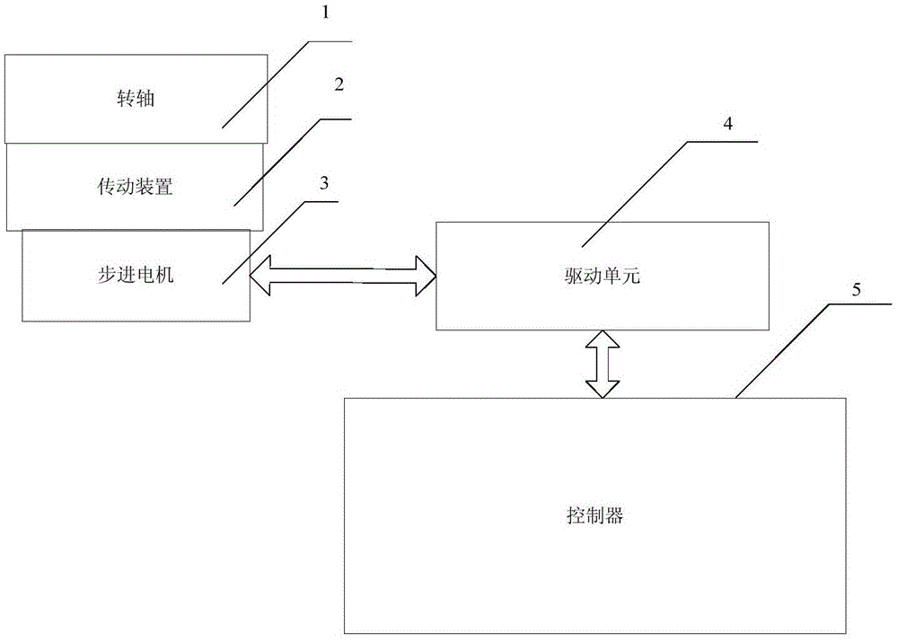
[0036] like figure 1 As shown, the present invention proposes a device for realizing the oscillating motion of the rotary shaft of the rotary table, which includes a rotary shaft oscillating motion device of a transmission device 2, a stepping motor 3, a drive unit 4 and a controller 5, wherein the stepping motor 3 passes through the transmission device 2 Connected to the rotating shaft 1, the controller 5 calculates the amplitude of the swinging motion of the rotating shaft in real time and converts it into a pulse signal and outputs it to the drive unit 4. The driving unit 4 converts the amplitude of the swinging motion of the rotating shaft into a driving signal in real time and outputs it to the stepping motor 3. 3 is rotated under the action of the driving signal, so that the rotating shaft 1 of the rotary table is driven to perform sinusoidal rocking motion through the transmission device 2 .

[0037] In order to further improve the swing accuracy and reduce the cost, th...


PUM


Abstract

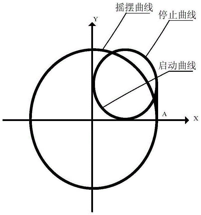
The invention relates to a device and method for realizing swing of a rotating shaft of a turn table. A stepping motor is connected with the rotating shaft via a transmission device, a controller generates pulse signals, a driving unit drives the stepping motor to rotate, and the stepping motor drives the rotating shaft to realize sine swing via the transmission device. A double-axis arc interpolation method is used, one is a practical axis, the other is a virtual axis, and the practical axis generates sinusoidal signals to realize start, swing and stop of the rotating shaft. According to the device and method, the swing precision of the rotating shaft is high, the frequency and amplitude are easy to adjust, half-range co-frequency cosine curve and sine curve are connected during start and stop, so that start and stop of the rotating shaft are smooth; and a servo period is used as the sampling interval, sampling points are more, and the distortion degree of the waveform is greatly reduced.

Description

technical field [0001] The invention relates to a device and a method for realizing the swinging motion of a rotating shaft, in particular to a device and a method for realizing the swinging motion of a rotating shaft through a stepping motor and a transmission device, and belongs to the field of swinging motion control of a rotary table. Background technique [0002] The swing motion of the rotary table generally has two schemes: the direct drive of the rotating shaft and the use of a reduction mechanism. The direct drive of the rotating shaft has high precision, but usually requires a high-torque motor, which will result in a large volume of the rotary table and high cost; the common use of the reduction mechanism is to use two There are two kinds of transmission devices, one is the mode of the reducer, which has a space error, resulting in low swing accuracy; the other is the cam transmission mode, which is not easy to adjust the frequency and amplitude, and the cam is eas...

Claims


Application Information

Patent Timeline
IPC IPC(8): G05D19/02
CPCG05D19/02
Inventor 董艳国周新敏曹雪立牟东慧朱日升
Owner BEIJING INST OF AEROSPACE CONTROL DEVICES
Learn More