Novel method for calibrating or calibrating impact velocity by using impact velocity measuring device

A technology of impact velocity and measuring device, applied in measuring device, impact test, testing of machine/structural components, etc., can solve the problems of large error, incorrectness, and the verification of impact velocity without considering the energy loss of indirect verification method. The effect of reducing calculation error, reducing acquisition error and improving frequency capture accuracy

Active Publication Date: 2016-05-04
安徽省计量科学研究院 +1
View PDF5 Cites 6 Cited by
  • Summary
  • Abstract
  • Description
  • Claims
  • Application Information

AI Technical Summary

Problems solved by technology

[0008] 2. The indicated value of the energy loss of the testing machine should not be used as the result of verifying the energy loss of the testing machine
That is to say, the indication value of the measured measuring instrument is used as the result of the verification instead of the verification by the measuring standard. Obviously, this method is incorrect.
[0013] 3. The energy loss caused by factors such as pointer friction, bearing friction and air resistance is not considered in the verification of impact velocity, and the above-mentioned energy consumption factors are considered when verifying energy loss, which makes the verification method of the regulations inconsistent.
[0014] In 7.3.1.1 direct verification method (7) of this regulation, the energy loss caused by pointer friction, bearing friction and air resistance has been verified, although the energy loss of the logarithmic display testing machine is based on the indicated value of the tested testing machine. check result, but use the Calculate impact velocity , the formula does not consider the impact of the above energy loss, which makes the verification method of the regulations inconsistent, and the impact velocity value measured by this method must be greater than the actual impact velocity value
[0015] 4. The indirect verification method has high verification cost, no operability and enforceability, and large errors, making it difficult to determine the compliance of the testing machine
If the standard sample is used to test the indication error according to the verification regulations, the verification fee is not enough to purchase the standard sample.
In addition, if the testing machine is classified according to the energy size, there are more than 20 specifications. In order to ensure the normal testing of the testing machine in the region, the testing agency needs to reserve a large number of standard samples of various measurement ranges, because the testing cost is much higher than the price. The inspection fee stipulated by the bureau has caused the inspection agencies in most parts of the country to lose money on one inspection, and the more they inspect, the more they lose.
Therefore, most of the domestic verification institutions hardly use standard samples to verify the error and repeatability of the indication value in the daily verification work, so that the procedure is basically inoperable and enforceable in actual work.
[0018] 2. The error of the indirect verification method is large, and it is difficult to judge the compliance of the testing machine
[0029] Therefore, when the indication error of the testing machine is in the undetermined area, it is impossible to judge the compliance of the testing machine

Method used


Image

  • Novel method for calibrating or calibrating impact velocity by using impact velocity measuring device
  • Novel method for calibrating or calibrating impact velocity by using impact velocity measuring device
  • Novel method for calibrating or calibrating impact velocity by using impact velocity measuring device

Examples


Embodiment Construction

[0039] The present invention will be further described below in conjunction with embodiment.

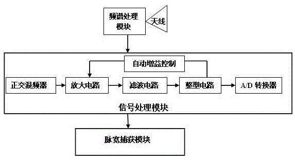
[0040] Such as figure 1 As shown, the shock velocity measuring device in the present invention includes a signal receiving antenna, a spectrum processing module and a signal processing module, and the signal processing module includes a quadrature mixer, an amplifying circuit, an automatic gain control circuit and A / D converter, the signal receiving antenna is a high-gain receiving antenna of 35dB, a filter circuit and a shaping circuit are sequentially connected to the signal between the amplifier circuit and the automatic gain control circuit, and the output end of the shaping circuit is connected to a main frequency 150MHz pulse width capture module.

[0041] A method for verifying or calibrating impact velocity, comprising the following steps: aligning the impact velocity measuring device with the motion track of an object to be verified or calibrated, turning on the impact velo...


PUM


Abstract

The invention discloses a novel method for calibrating or calibrating impact velocity by using an impact velocity measuring device. The impact velocity measuring device comprises a signal receiving antenna, a spectrum processing module and a signal processing module, wherein the signal processing module comprises a quadrature mixer, an amplification circuit, an automatic gain control circuit and an A/D converter which are in signal connection with one another sequentially. The impact velocity measuring device is characterized in that the signal receiving antenna is a 35dB high-gain receiving antenna; a filtering circuit and a shaping circuit are in signal connection sequentially between the amplification circuit and the automatic gain control circuit; and the output end of the shaping circuit is connected with a pulse width capture module the main frequency of which is 150MHz. According to the method of the invention, a 0.5-to-10 m/s measuring range can be obtained accurately through adopting the high-gain receiving antenna and pulse width capture; and the pulse width capture module (eCAP) the main frequency of which is as high as 150MHz is adopted to perform acquisition, frequency capture precision can be greatly improved, acquisition errors can be lowered, and high-precision velocity measurement can be realized.

Description

technical field [0001] The invention relates to the technical field of measurement and testing, in particular to a method for verifying or calibrating impact velocity using an impact velocity measuring device. Background technique [0002] In the horizontal impact test (horizontal, inclined plane impact test) of transport packages, the impact velocity is the key parameter to determine whether the test strength value of the inclined plane impact testing machine is accurate or not. Therefore, it is very important to use the impact velocity measuring device to verify or calibrate the impact velocity of the test system, especially for low-speed measurement, which requires accuracy, high resolution, and accurate tracking. The distance from the object to the impact surface is relatively short, and the sensor sensing time is shortened The output speed is affected by the vibration, the error is large, and the laser speed measurement is difficult to capture the target. The speed meas...

Claims


Application Information

Patent Timeline
Patent Type & Authority Applications(China)
IPC IPC(8): G01M7/08
CPCG01M7/08
Inventor 王强陈镇金美峰黄利君贺德溪宋淮北李鸣
Owner 安徽省计量科学研究院
Why Eureka
Try Eureka