
Chest drainage systems and methods

一种胸腔、胸膜腔的技术,应用在创口引流器、抽取汲送系统、其他医疗器械等方向,能够解决患者瞬时负压度高等问题

Inactive Publication Date: 2016-04-27
ATRIUM MEDICAL
View PDF24 Cites 5 Cited by
  • Summary
  • Abstract
  • Description
  • Claims
  • Application Information

AI Technical Summary

Problems solved by technology

To clear the blockage, the caregiver "squeezes" the tube in an attempt to reopen it, however, this procedure often results in a momentary high negative pressure on the patient

Method used


Image

  • Chest drainage systems and methods
  • Chest drainage systems and methods
  • Chest drainage systems and methods

Examples


Embodiment Construction

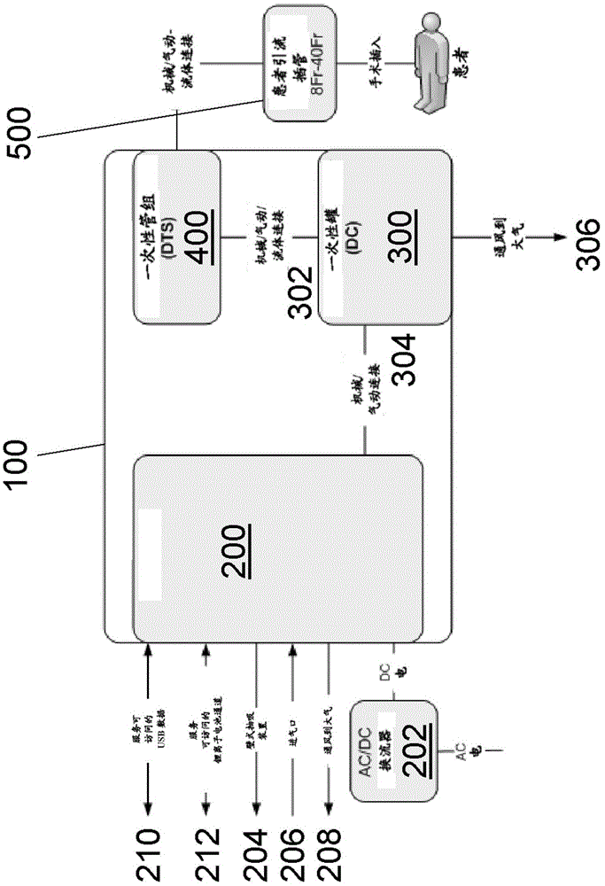
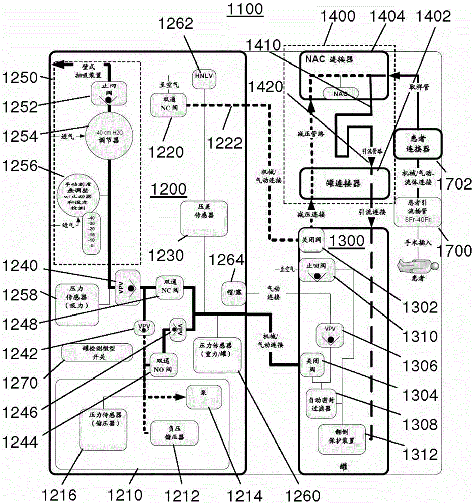
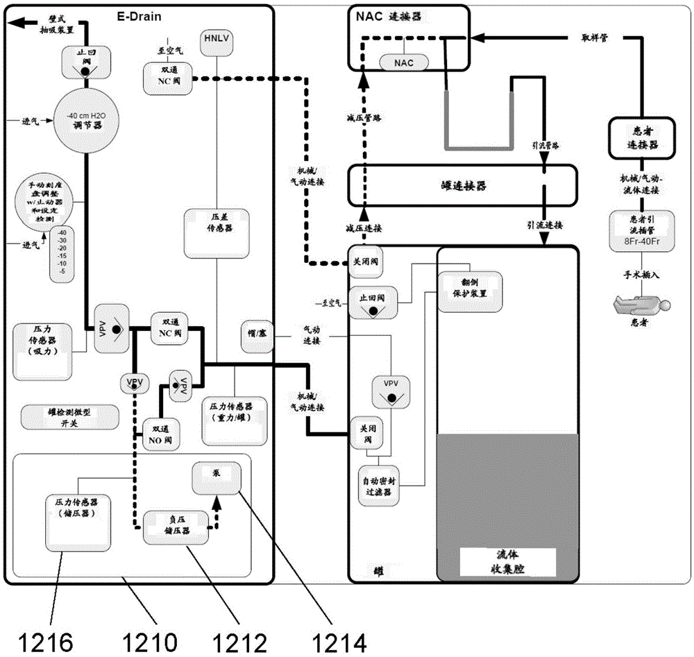
[0092] The invention will now be described with reference to a selected number of embodiments shown in the drawings. It should be understood that the scope and spirit of the present invention is not limited to the illustrated embodiments. It should also be understood that the drawings are not to any particular scale or size. Furthermore, any dimensions referred to in describing the illustrated embodiments are provided for illustrative purposes only. The invention is not limited to any specific dimensions, materials or other details of the shown embodiments.

[0093] The exemplary systems and methods described herein can be used to drain or otherwise recover fluid from a patient. The illustrated systems and methods are described herein primarily with reference to draining the pleural cavity of a patient, or for convenience, in accordance with an embodiment of the present invention chosen for purposes of illustration and description. However, those skilled in the art should u...


PUM


Abstract

A chest drainage system includes a collection device and a fluid pathway configured to extend from the collection device to a patient. A pressure source is configured to selectively provide sub-atmospheric pressure to the fluid pathway. The system is configured to introduce sub-atmospheric pressure from the pressure source at a substantially constant target pressure and at a dynamic pressure that varies from the target pressure. A method is also disclosed for draining a pleural cavity of a patient. The method involves applying dynamic pressure to the pleural cavity of a patient by changing sub-atmospheric pressure applied to the patient such that the patient's pleura moves without any or limited patient activity, thus facilitating removal of loculated fluid from the pleural cavity. The method may involve the use of the chest drain system.

Description

[0001] Cross References to Related Applications [0002] This application claims the benefit of priority to US Provisional Patent Application No. 61 / 856,427, filed July 19, 2013, which is hereby incorporated by reference in its entirety. technical field [0003] The field of the invention relates generally to medical drainage systems and, more particularly, to chest drainage systems. Background technique [0004] A number of fluid recovery systems have been developed for removing fluid, such as air and / or blood, from a patient. An example of such a fluid recovery system is a chest drainage system. Chest drainage systems are intended to remove fluid from the pleural or mediastinal cavity and restore the sub-atmospheric pressure normally present in the pleural cavity. The system is generally adapted to allow suction to be applied to the pleural cavity to facilitate, inter alia, removal of fluid from the pleural cavity. Once the fluid is removed, the pleural cavity is allowe...

Claims


Application Information

Patent Timeline
Patent Type & Authority Applications(China)
IPC IPC(8): A61M27/00
CPCA61M2205/15A61M2205/50A61M2210/101A61M2209/082A61M1/73A61M1/75A61M1/74A61M1/742A61M2205/3331A61M2205/52
Inventor G·皮特菲尔德
Owner ATRIUM MEDICAL
Learn More