
Atomic clock frequency and phase adjustment device

A phase adjustment, atomic clock technology, applied in the direction of automatic power control, electrical components, etc., can solve the problem of increasing the cumulative error of punctuality, and achieve the effect of high resolution

Inactive Publication Date: 2016-04-20
BEIJING INST OF RADIO METROLOGY & MEASUREMENT
View PDF4 Cites 3 Cited by
  • Summary
  • Abstract
  • Description
  • Claims
  • Application Information

AI Technical Summary

Benefits of technology

This technology helps maintain accurate timing by allowing each atom inside it to have an exact same number of times per second (Hz). By measuring these frequencies with various instruments like oscillators or optical detectors, they are able to accurately determine how long things take place within seconds.

Problems solved by technology

This patented technical problem addressed in this patents relates to improving the performance (accuracy) and reliability of an electronic device's timing function when exposed to varying environmental conditions over its lifetime.

Method used


Image

  • Atomic clock frequency and phase adjustment device

Examples

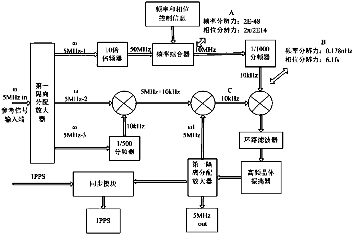

Embodiment Construction

[0026] In order to illustrate the present invention more clearly, the present invention will be further described below in conjunction with preferred embodiments and accompanying drawings. Similar parts in the figures are denoted by the same reference numerals. Those skilled in the art should understand that the content specifically described below is illustrative rather than restrictive, and should not limit the protection scope of the present invention.

[0027] Such as figure 1 As shown, the present invention discloses an atomic clock frequency and phase adjustment device, which includes: a reference signal input terminal for inputting a 5MHz signal, and a first isolation allocation for dividing the input 5MHz reference signal into three 5MHz signals The amplifier, based on external frequency and phase control information, uses the first 5MHz frequency multiplied by 10 as the clock, and outputs the frequency synthesis module of the 10MHz signal. The second 5MHz signal is s...


PUM


Abstract

The invention discloses an atomic clock frequency and phase adjustment device. The device includes a reference signal input end, a first isolation distribution amplifier which divides inputted 5MHz reference signals into three paths of 5MHz signals, a frequency synthesis module which outputs 10MHz signals based on external frequency and phase control information and with the first path of 5MHz signals which have been subjected to 10 times of frequency multiplication adopted as time, a frequency mixing unit which mixes the second path of 5MHz signals with the third path of 5MHz signals which have been subjected to 1/500 frequency division, 5MHz signals and 10MHz signals which have been subjected to 1/1000 frequency division and are outputted by the frequency synthesizer, and then, outputs 10MHz frequency-mixed signals, and a high-stability crystal oscillator which outputs 5MHz signals based on the 10MHz frequency-mixed signals.

Description


Claims


Application Information

Patent Timeline
Owner BEIJING INST OF RADIO METROLOGY & MEASUREMENT
Learn More