
Branch Line Directional Coupling Distributor

A technology of directional coupling and distributor, applied in the direction of waveguide devices, circuits, connecting devices, etc.

Active Publication Date: 2020-04-07
FURUNO ELECTRIC CO LTD
View PDF3 Cites 0 Cited by
  • Summary
  • Abstract
  • Description
  • Claims
  • Application Information

AI Technical Summary

Problems solved by technology

In addition, there is a 90° phase difference between the signal output from the second port 112 and the signal output from the third port 113

Method used


Image

  • Branch Line Directional Coupling Distributor
  • Branch Line Directional Coupling Distributor
  • Branch Line Directional Coupling Distributor

Examples


Embodiment Construction

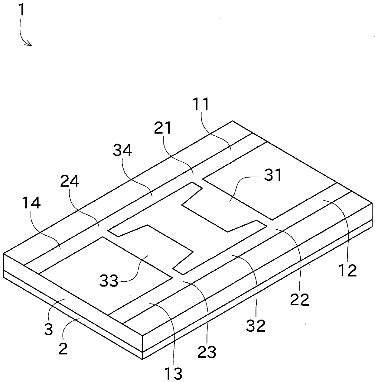
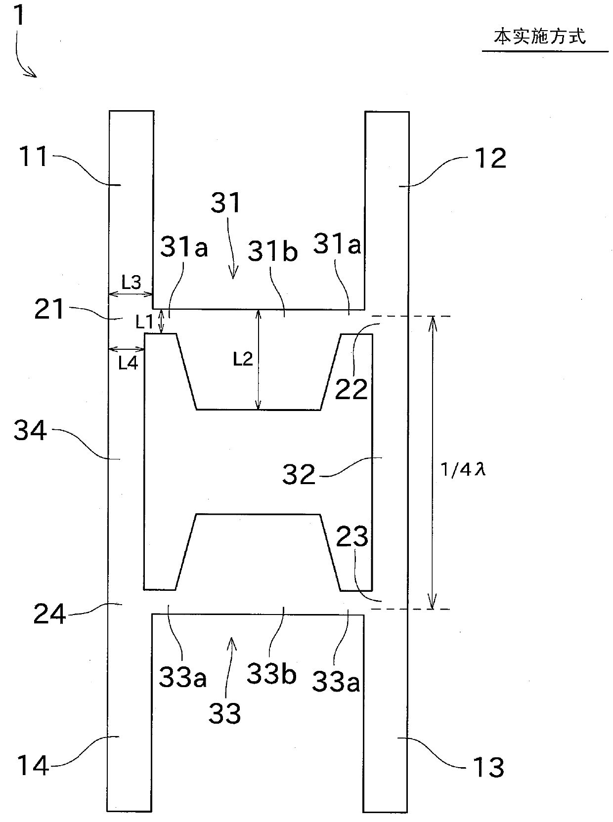
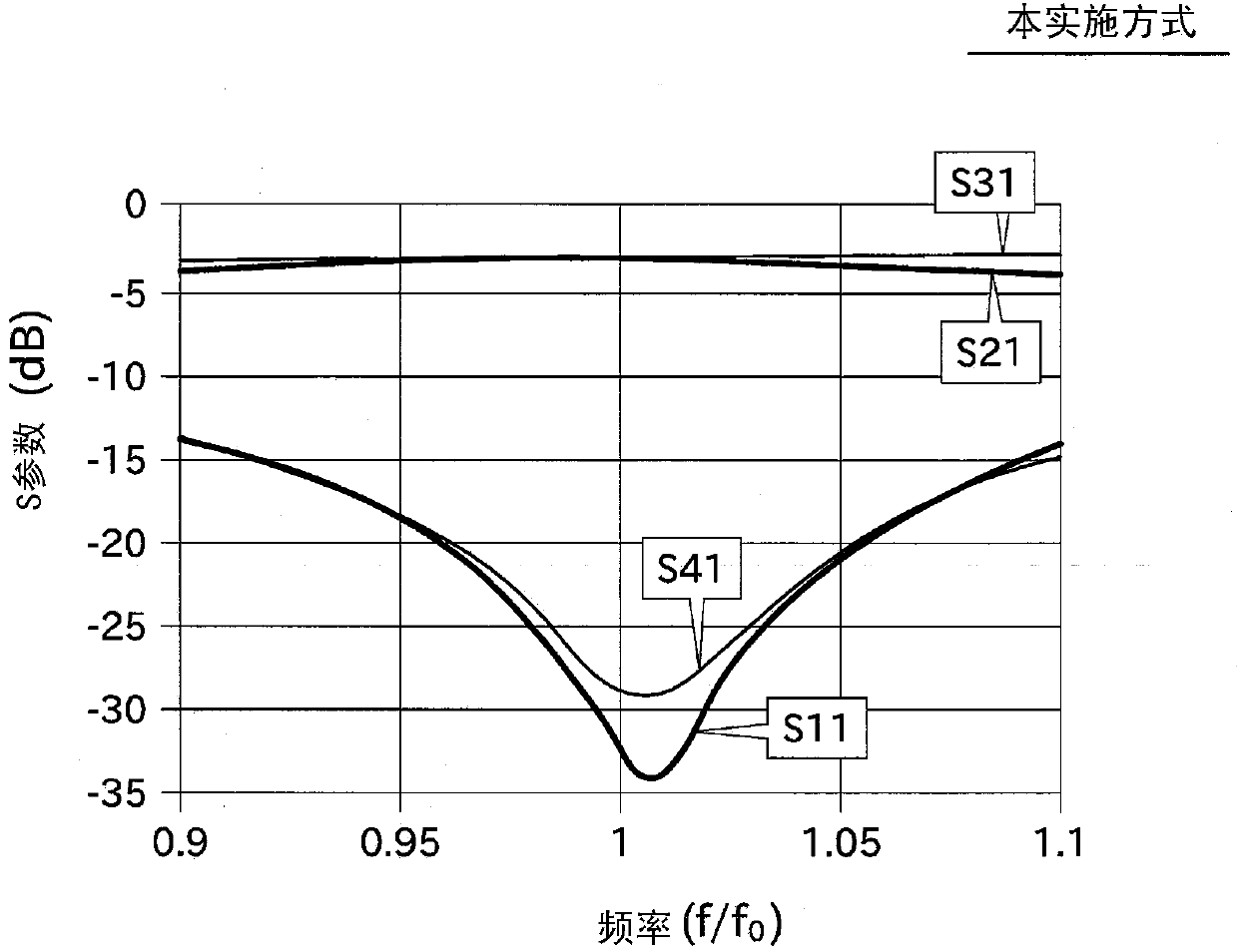
[0046] Next, refer to figure 1 and figure 2 Embodiments of the present invention will be described. In the following description, when explaining equality, parallelism, and perpendicularity, etc., not only equality, parallelism, and perpendicularity in the strict sense, but also some degree of error may occur. In this specification, even when such a slight error occurs, it is regarded as corresponding to equality, parallelism, perpendicularity, and the like.

[0047]The branch line type directional coupling distributor (hereinafter referred to as "directional coupling distributor") of the first embodiment is provided in a radar device. Specifically, it is provided in a circularly polarized wave generating device that generates circularly polarized waves, or a receiving circuit that receives reflected waves (microwaves) reflected by a target object as a transmitted wave, or the like. In addition, the directional coupling distributor 1 is not limited to a radar device, and ...


PUM


Abstract

The invention provides a branch-line directional coupling distributor, the length starting point needed by a transmission line is considered, and therefore the branch-line directional coupling distributor is miniaturized. The directional coupling distributor (1) is provided with four ports used for inputting and outputting microwaves, four branch parts which are branched into two paths from the ports, and four transmission lines connecting the branch parts. The four transmission lines comprise a first transmission line (31) and a third transmission line (33) serving as multi-section transmission lines. In the multi-section transmission lines, the line width of the end part of the transmission line is smaller than the line width of the central part of the transmission line. A second transmission line (32) and a fourth transmission line (34) serve as connecting transmission lines and are connected with the multi-section transmission lines through the branch parts, and the distance between the outer side relative to the central part of the end part of one multi-section transmission line and the outer side relative to the central part of the end part of the other multi-section transmission line is equal to 1 / 4 wave length.

Description

technical field [0001] The present invention relates to a branch line type directional coupler for coupling or distributing microwaves. Background technique [0002] It has long been known that, as Figure 11 The shown branch line type directional coupling distributor (hereinafter, referred to as "directional coupling distributor"). Figure 11 The directional coupling distributor 100 is composed of 4 ports, 4 T-shaped branches, and 4 transmission lines. [0003] Specifically, the first branch portion 121 connects the fourth transmission line 134 , the first port 111 , and the first transmission line 131 . The second branch part 122 connects the first transmission line 131 , the second port 112 and the second transmission line 132 . The third branch part 123 connects the second transmission line 132 , the third port 113 and the third transmission line 133 . The fourth branch part 124 connects the third transmission line 133 , the fourth port 114 and the fourth transmission ...

Claims


Application Information

Patent Timeline
Patent Type & Authority Patents(China)
IPC IPC(8): H01P5/18
Inventor 井上修平饭尾宪一
Owner FURUNO ELECTRIC CO LTD
Learn More