Eureka AIR delivers breakthrough ideas for toughest innovation challenges, trusted by R&D personnel around the world.

Cylinder type annealing furnace

An annealing furnace and caisson technology, which is applied in the direction of furnaces, furnace types, heat treatment furnaces, etc., can solve the problems of reducing work efficiency and increasing heating time, and achieves the effects of thorough annealing, uniform heating, and better annealing effect

Inactive Publication Date: 2016-04-20
CHONGQING YONGFU WIRE & CABLE CO LTD
View PDF8 Cites 0 Cited by
  • Summary
  • Abstract
  • Description
  • Claims
  • Application Information

AI Technical Summary

Problems solved by technology

To make the hardness of the inner and outer aluminum conductors the same, the heating time needs to be increased, which reduces the work efficiency

Method used


Image

  • Cylinder type annealing furnace
  • Cylinder type annealing furnace
  • Cylinder type annealing furnace

Examples


Embodiment 1

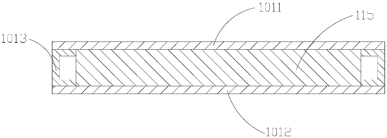
[0042] Embodiment 1, with reference to Figure 1 to Figure 3

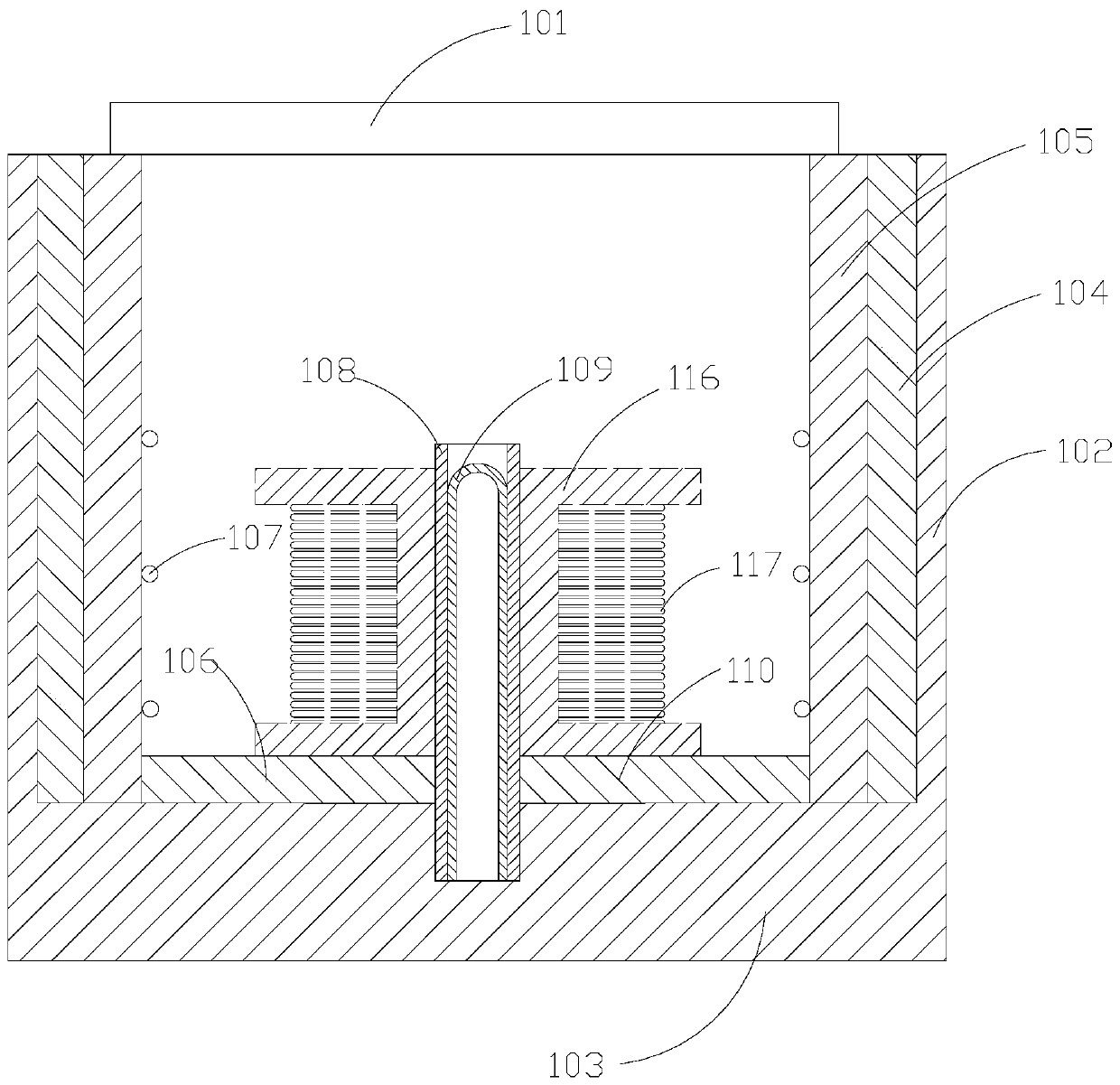
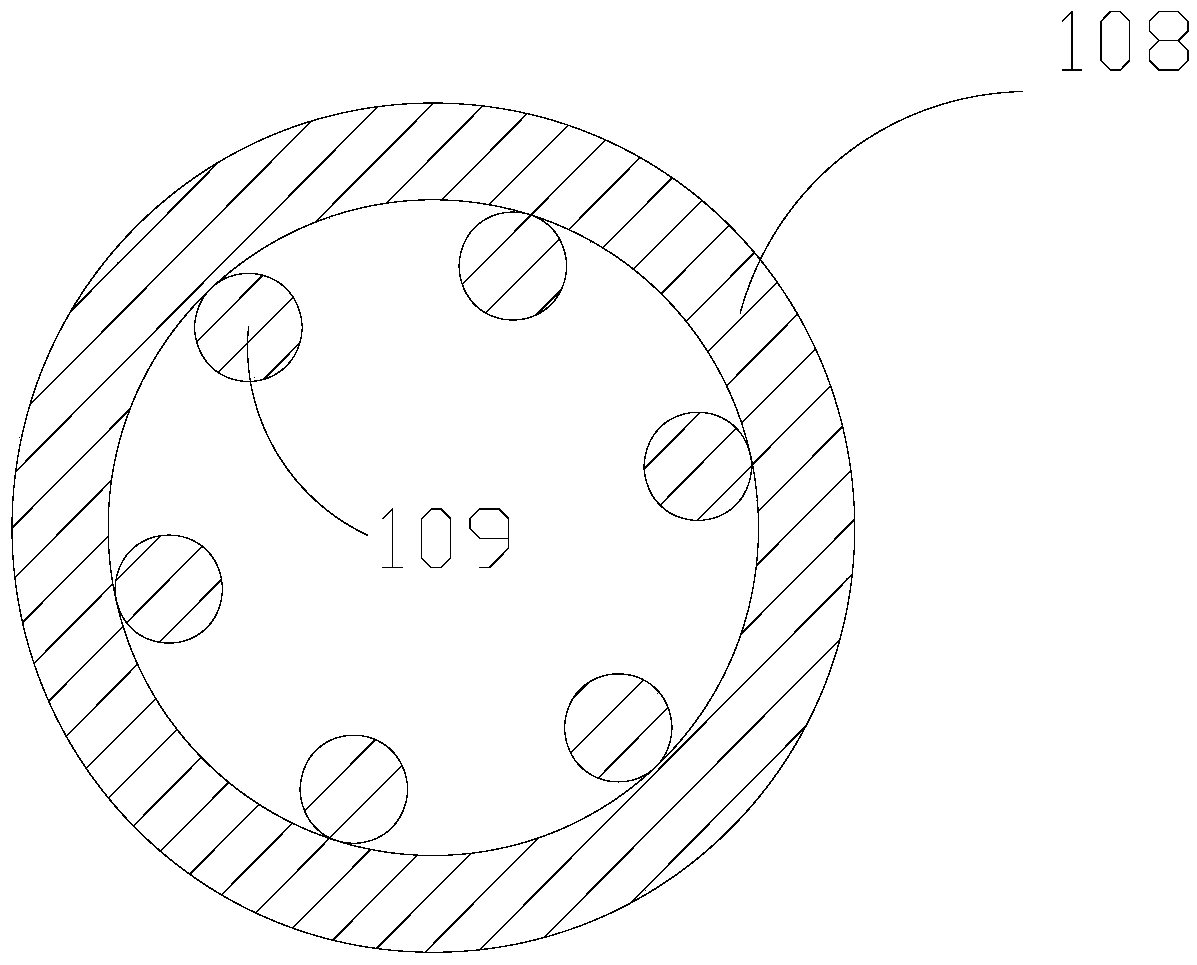
[0043] Such as figure 1 As shown, a caisson type annealing furnace includes a furnace body and a furnace cover 101, the furnace body includes a furnace side wall 102 and a furnace bottom wall 103, the furnace side wall 102 is provided with a first thermal insulation lining 104, the The first thermal insulation lining 104 is provided with a refractory lining 105, the furnace cover 101 is covered on the first thermal insulation lining 104, the upper surface of the furnace bottom wall 103 is provided with a second thermal insulation lining 106, and the refractory lining 105 is provided with a first resistance wire 107, and the furnace body is provided with a vertical cylinder 108, and a second resistance wire 109 is provided in the vertical cylinder 108.

[0044] When the aluminum conductor 117 is annealed, the aluminum conductor 117 is wound on the "I" shaped annealing disk 116, and the annealing disk 116 is put in...

Embodiment 2

[0051] Embodiment 2, with reference to Figure 4 to Figure 6

[0052] The implementation principles and technical effects of the device provided by the embodiment of the present invention are the same as those of the foregoing method embodiment. For brief description, for the parts not mentioned in the device embodiment, reference may be made to the corresponding content in the foregoing method embodiment.

[0053] In this embodiment, the furnace body is also provided with a turntable 110, such as Figure 5 As shown, the turntable 110 is in the shape of "I" as a whole. The turntable 110 includes a base 1101 and a disc 1102. The base 1101 is a T-shaped structure. The disc 1102 is screwed to the base 1101. The bottom of the base 1101 is provided with It is located in the bottom wall of the furnace body and can rotate around its own axis.

[0054] Such as Figure 4 As shown, a motor 111 is arranged in the bottom wall of the furnace body, the output shaft of the motor 111 is co...


PUM


Abstract

The invention provides a cylinder type annealing furnace, and belongs to the field of heat treatment equipment. The cylinder type annealing furnace comprises a furnace body and a furnace cap, wherein the furnace body comprises a furnace side wall and a furnace bottom wall; a first insulating lining is arranged in the furnace side wall, a refractory lining is arranged in the first insulating lining; the furnace cap covers the first insulating lining; a second insulating lining is arranged on the upper surface of the furnace bottom wall; a first resistance wire is arranged on the refractory lining; and a vertical tube is arranged in the furnace body, and a second resistance wire is arranged in the vertical tube. According to the annealing furnace, an inner ring aluminum conductor and an outer ring aluminum conductor can be heated at the same time, so that same hardness of the inner and outer ring aluminum conductors after annealing treatment can be guaranteed.

Description

technical field [0001] The invention relates to the field of heat treatment equipment, in particular to a caisson type annealing furnace. Background technique [0002] Annealing is a metal heat treatment process, which refers to heating the metal to a certain temperature, keeping it for a sufficient time, and then cooling it at an appropriate speed to achieve the purpose of reducing the hardness of the metal. When the aluminum conductor is annealed, it is generally necessary to wind the aluminum conductor on the annealing disk, put the aluminum conductor and the annealing disk together into the annealing furnace, and perform annealing treatment. During the annealing process, the aluminum conductor wound on the outer ring The heat is faster, and the aluminum conductor wound on the outer ring is heated slower. After the annealing treatment is completed, the hardness of the aluminum conductor of the inner ring and the aluminum conductor of the outer ring will be different. To ...

Claims


Application Information

Patent Timeline
IPC IPC(8): C21D1/26C21D9/54C22F1/04
CPCC21D1/26C21D9/54C22F1/04
Inventor 陈光远
Owner CHONGQING YONGFU WIRE & CABLE CO LTD
Why Eureka
Eureka Blog
Learn More