Folding propeller for above-water platform
A water platform, foldable technology, applied in ship propulsion, propulsion components, propulsion engine, etc., can solve problems such as limitations, and achieve the effects of reasonable structure, easy folding and storage, and high safety
- Summary
- Abstract
- Description
- Claims
- Application Information
AI Technical Summary
Problems solved by technology
Method used
Image
Examples
Embodiment 1
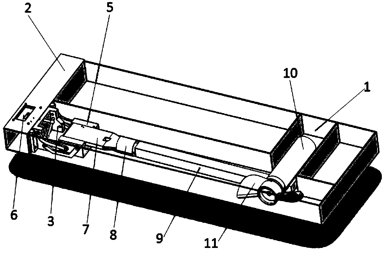
[0028] Such as figure 1 As shown, it is a schematic structural diagram of the working state of Embodiment 1 of the present invention, including a water platform chamber 1, a beam 2, a flip arm 4, a fixed block 5, a fixing mechanism 6, a motor rod upper arm 7, a steering motor 8, and a motor rod lower arm 9, motor 10, propeller 11. In the figure, the foldable propeller has turned over from the water platform chamber 1 and entered the working state. Wherein, the overturning arm 4 turns over the fixed block 5 onto the crossbeam 2, and is connected and fixed with the fixing mechanism 6; the motor rod composed of the motor rod upper arm 7 and the motor rod lower arm 9 faces downward; the direction of the motor 10 and the propeller 11 is passed through the The steering motor 8 in the motor rod upper arm 7 is adjusted to the direct rear towards the water platform. In this way, the foldable propeller that is powered on can start the motor, generate thrust, and drive the water platfo...
Embodiment 2
[0032] Such as Figure 6 , Figure 7 , Figure 8 Shown is a schematic structural diagram of Embodiment 2 of the present invention. In this example, if Figure 6 As shown, a turning joint 12 is added at one end of the outer surface of the fixed block 5, and a connecting joint 13 is connected with the upper arm 7 of the motor rod. After the fixed block 5 is connected and fixed with the fixing mechanism 6, the turning joint 12 can turn over laterally, driving the position of the motor rod to flip laterally, and the connecting joint 13 turns the whole motor rod downward. Such as Figure 7 As shown, the turning joint 12 has been turned horizontally by 180°C, and the connecting joint 13 has turned the entire motor shaft vertically downward, so that the motor shaft that was originally on the side of the water platform has been moved to the middle of the water platform. Figure 8 Shown is the working state of embodiment 2, the folding propeller is in the middle of the water platf...
Embodiment 3
[0034] Such as Figure 9 , Figure 10 , Figure 11 Shown is a schematic structural diagram of Embodiment 3 of the present invention. What this embodiment shows is another kind of scheme of adding flip joints on the fixed block 5, Figure 9 Among them, one end of the top groove of the fixed block 5 is a turning joint 14, and a connecting joint 15 is connected with the upper arm 7 of the motor rod. After the fixed block 5 is connected and fixed with the fixed mechanism 6, the turning joint 14 on the top of the fixed block 5 is turned over laterally, which drives the position of the motor rod to flip laterally, and the connecting joint 15 turns the whole motor rod downward. Figure 10 In the process, turn the turning joint 13 on the top of the fixed block 5 horizontally by 180°C, then turn the connecting joint 15, and put the entire motor shaft vertically downward. Figure 11 Shown is the working state of embodiment 3, because the flip joint 14 flips the folding propeller to ...
PUM
 Abstract
Description
Claims
Application Information
 - R&D
- Intellectual Property
- Life Sciences
- Materials
- Tech Scout
- Unparalleled Data Quality
- Higher Quality Content
- 60% Fewer Hallucinations
Browse by: Latest US Patents, China's latest patents, Technical Efficacy Thesaurus, Application Domain, Technology Topic, Popular Technical Reports.
© 2025 PatSnap. All rights reserved.Legal|Privacy policy|Modern Slavery Act Transparency Statement|Sitemap|About US| Contact US: help@patsnap.com


