
Drilling machine and its tool changing method

A technology of drilling machine and tool holder, which is applied to metal processing machinery parts, clamping, supporting and other directions, can solve the problems of low equipment moving rate, low drilling efficiency, occupying drilling time, etc., and save waiting for replacement. The effect of cutting tool time, improving drilling efficiency and equipment mobilization rate

Active Publication Date: 2018-06-22
SUZHOU VEGA TECH CO LTD
View PDF8 Cites 2 Cited by
  • Summary
  • Abstract
  • Description
  • Claims
  • Application Information

AI Technical Summary

Problems solved by technology

[0003] However, in this traditional structure, when the tool is changed, the drilling system needs to stop working, and the drilling can only continue after the tool change system completes the tool change. Since such a tool change action takes up a lot of real drilling time of the equipment, the drilling The efficiency is low, and the equipment marriage rate is not high

Method used


Image

  • Drilling machine and its tool changing method
  • Drilling machine and its tool changing method
  • Drilling machine and its tool changing method

Examples


Embodiment Construction

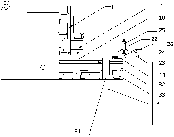
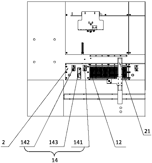
[0028] In order to make the object, technical solution and advantages of the present invention clearer, the present invention will be described in detail below in conjunction with the accompanying drawings and specific embodiments.

[0029] Such as figure 2 and image 3 As shown, the drilling machine 100 of the present invention is a high-efficiency PCB drilling machine for drilling the workbench 10 . The tool change mode of PCB drilling machine is mainly divided into two types: one is the upper tool change mode represented by European equipment, and the other is the lower tool change mode represented by Japanese and Taiwan equipment. The steps and methods of these two tool change modes are basically the same, and the following part of the manual will take the following tool change mode as an example to describe in detail.

[0030] The drilling machine 100 includes a drilling system 1 and a tool changing system 2 that can act independently at the same time. The drilling sys...


PUM


Abstract

The invention provides a drilling machine and a tool changing method thereof. The drilling machine comprises a drilling system and a tool changing system, wherein the drilling system and the tool changing system can simultaneously act independently; the drilling system comprises at least one spindle capable of moving in the up-down direction; the spindles share the tool changing system; the tool changing system comprises a tool magazine device and a manipulator device assembled on the tool magazine device; the tool magazine device comprises tools, a tool pan and a tool apron; the tool pan is used for storing the tools; and the manipulator device comprises a manipulator for capturing and placing the tools. The manipulator captures the tools from the tool pan and places the tools on the tool apron, when tool changing is required for the spindles, the tool changing system is driven by a motor and moves to tool changing positions, and the spindles descend to capture the tools so as to realize tool changing.

Description

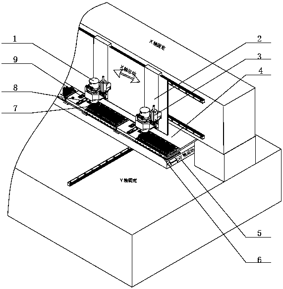
technical field [0001] The invention relates to a drilling machine and a tool changing method thereof. Background technique [0002] The drilling system and the tool change system of the traditional PCB drilling machine are not independent working systems. The tool change system is connected in series as a subsystem of the drilling system during the drilling process of the equipment. When the tool needs to be replaced, the drilling system stops working and enters the tool change system, and continues drilling after the tool change is completed. The tool change structure of the traditional PCB drilling machine is as attached in the manual figure 1 As shown, the manipulator 3 and the main shaft 1 are assembled on the X-axis motion mechanism 2 of the equipment, so that the X-axis motion can be realized under the drive of the X-axis motor through the aforementioned X-axis motion mechanism 2; the tool magazine 6 is assembled on the workbench 4 and A Y-axis motion mechanism 5 is...

Claims


Application Information

Patent Timeline
Patent Type & Authority Patents(China)
IPC IPC(8): B23Q3/157
Inventor 常远赵葵
Owner SUZHOU VEGA TECH CO LTD
Learn More