Peristaltic pump with reduced pulsation and application of said peristaltic pump

A technology of peristaltic pumps and pulsation effects, applied to pumps with flexible working elements, pumps, pump components, etc., can solve problems such as high failure probability and pump wear

Active Publication Date: 2017-08-11
BAUSCH STROEBEL MASCHFAB ILSHOFEN GMBH CO KG
View PDF8 Cites 0 Cited by
  • Summary
  • Abstract
  • Description
  • Claims
  • Application Information

AI Technical Summary

Problems solved by technology

A disadvantage of the last two mentioned solutions is that the hose squeeze mechanism must be designed to be movable in the rotating part, which leads to wear and a higher probability of failure of the pump

Method used


Image

  • Peristaltic pump with reduced pulsation and application of said peristaltic pump
  • Peristaltic pump with reduced pulsation and application of said peristaltic pump
  • Peristaltic pump with reduced pulsation and application of said peristaltic pump

Examples


Embodiment Construction

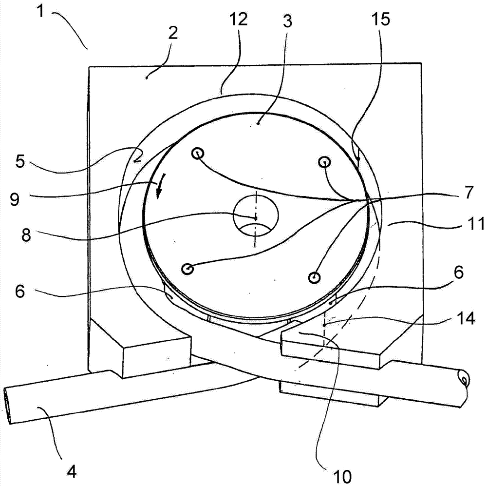
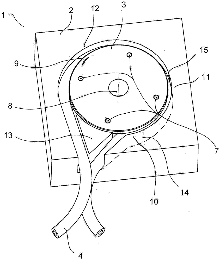
[0045] figure 1 A perspective view is shown of a peristaltic pump 1 comprising a saddle 2 inside which a rotor 3 is arranged. The hose 4 is arranged in the gap between the saddle inner surface 5 and the peripheral surface of the rotary part 3 . Arranged on the periphery of the rotary part 3 are four hose squeezing means 6 largely covered by the rotary part 3 . The hose squeezing means 6 are designed as rollers, which are each rotatable about the axis 7 of the rotor. The hose squeeze mechanism 6 engages in the hose 4 and compresses the hose so that it is at least temporarily closed by the hose squeeze mechanism 6 . The hose 4 is fixedly arranged in the saddle 2 . During the rotation of the rotor 3 , the hose squeezing mechanism 6 travels along the hose 4 and compresses it before the saddle inner face 5 . The illustrated peristaltic pump 1 has a winding angle of approximately 360°, the ends of the hoses 4 emerging from the peristaltic pump 1 crossing one another in or shortl...


PUM


Abstract

The invention relates to a peristaltic pump (1) having a saddle and a rotor (3) rotatable in the saddle, between which a hose (4) is arranged. The rotary part (3) has a hose squeeze mechanism (6), which follows the rotation of the rotary part (3) over the hose (4) and thereby delivers the conveying fluid. The pulsation effect occurs when the hose squeeze mechanism (6) emerges from the hose (4). According to the invention, this pulsation effect is suppressed by suitably shaping the saddle inner surface ( 5 ) against which the hose ( 4 ) rests. In addition, the pulsation effect can be reduced or avoided by adapting the regulation of the rotational speed of the rotor, by suitable selection of the delivery end position when metering the delivery medium, or by determining a specific invariable delivery end position. Furthermore, it is proposed to use such a peristaltic pump ( 1 ) for metering.

Description

technical field [0001] The invention relates to a peristaltic pump for conveying a conveying medium of a fluid through a hose, which has a saddle with an arcuately shaped saddle inner face and a rotor arranged in the saddle rotatably about an axis of rotation, said The swivel part comprises a plurality of hose pressing means, distributed angularly around the swivel axis, arranged at least temporarily opposite the inner surface of the saddle, in order to act from the outside on the hose to be arranged between the inner saddle and the swivel part. , so that the corresponding local narrowing of the passage cross-section of the hose due to the external loading of the hose by the hose squeeze mechanism can move along the inner surface of the saddle with the relevant hose squeeze mechanism when the rotating part rotates , in order to convey the conveying medium in the hose, wherein the saddle has, in the stated order, a sinking area along the saddle inner surface of preferably 30°, ...

Claims


Application Information

Patent Timeline
Patent Type & Authority Patents(China)
IPC IPC(8): F04B43/12
CPCF04B43/12F04B43/1253F04B43/1261F04B11/00
Inventor S·阿克曼H·鲍尔
Owner BAUSCH STROEBEL MASCHFAB ILSHOFEN GMBH CO KG
Why Eureka
Try Eureka