
Multi-purpose assembly fixture for skewed laminated stator core

A stator core and assembly fixture technology, which is applied in the manufacture of stator/rotor bodies, electromechanical devices, and motor generators. It can solve the problems of inaccurate torsion angle of the chute, high labor intensity, and cumbersome operation, and achieve skew Precise angle, extended scope of application, and convenient assembly

Active Publication Date: 2018-02-02
GUIYANG AVIATION MOTOR
View PDF7 Cites 0 Cited by
  • Summary
  • Abstract
  • Description
  • Claims
  • Application Information

AI Technical Summary

Problems solved by technology

[0002] As we all know, for medium and small permanent magnet synchronous motors, especially permanent magnet motors with built-in magnetic steel, the most commonly used method is to use the stator chute structure to weaken the cogging effect; at present, it is usually formed by manual assembly and lamination The stator chute has defects such as high labor intensity, low efficiency, and inaccurate torsion angle of the chute. For this reason, a utility model patent with the announcement number "CN103259378A" and the name "Slant-free lamination device for stator core with chute" is disclosed A press-fitting fixture for skewed laminated stator cores is proposed, which consists of a core barrel fixed on the base, a number of tapered grooves vertically opened on the outer wall of the core barrel, positioning keys fixed in each tapered groove, and connecting The bolt structure of the base and the pressure plate is relatively simple in this patent, but it is still a manual operation device, which is labor-intensive, cumbersome and inefficient.

Method used


Image

  • Multi-purpose assembly fixture for skewed laminated stator core
  • Multi-purpose assembly fixture for skewed laminated stator core
  • Multi-purpose assembly fixture for skewed laminated stator core

Examples


Embodiment Construction

[0014] The present invention will be further described below in conjunction with the accompanying drawings and specific embodiments.

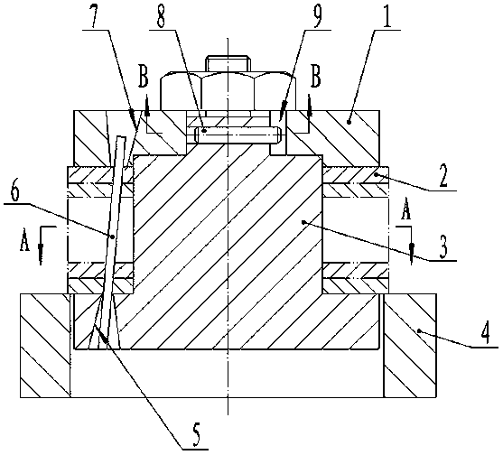
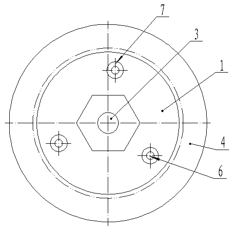
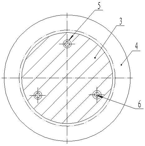
[0015] as attached Figure 1~6 As shown, the pressure plate 1 is set on the stepped positioning mandrel 3 through the female stop, and the pressure plate 1 has three upper and lower first horn holes 7 evenly distributed with the axis of the positioning mandrel 3 as the center of the circle. On the mandrel 3 there are three second horn holes 5 that are evenly distributed with the axis as the center of the circle; the first horn hole 7 and the corresponding second horn hole 5 are staggered with the axis as the center of the circle. Angle, the pin 6 is inserted between the corresponding first horn hole 7 and the second horn hole 5 . The bolt 6 is clearance fit with the second horn hole 5 and the first horn hole 7 .

[0016] In order to facilitate the clamping of the laminated stator core sheets 2, an inner hole (not shown in the figure) is opene...


PUM


Abstract

The invention discloses a multi-purpose assembly jig for a skewed and laminated stator core, belongs to a motor manufacturing tooling, and aims at providing the multi-purpose assembly jig for the skewed and laminated stator core, which is good in assembly accuracy, simple in structure, convenient to operate and high in efficiency. The multi-purpose assembly jig comprises a positioning mandrel and a pressure plate, wherein the pressure plate is matched with the mandrel; the pressure plate (1) is arranged on the positioning mandrel (3) through a stopping opening, and is provided with three first bellmouth orifices (7) which are evenly distributed by taking the axis of the positioning mandrel (3) as the circle center; the positioning mandrel (3) is provided with three second bellmouth orifices (5) which are evenly distributed by taking the axis of the circle center; an angle is staggered between each first bellmouth orifice (7) and the corresponding second bellmouth orifice (5) by taking the axis as the circle center; and a bolt (6) is inserted between the corresponding first bellmouth orifice (7) and second bellmouth orifice (5). The multi-purpose assembly jig can be applied to a plurality of procedures of laminating, milling, welding and the like, and is a laminated stator assembly jig.

Description

technical field [0001] The invention relates to a clamp for pressing a laminated stator, in particular to a clamp for assembling a skewed laminated stator core, which belongs to the tooling for motor manufacturing. Background technique [0002] As we all know, for medium and small permanent magnet synchronous motors, especially permanent magnet motors with built-in magnetic steel, the most commonly used method is to use the stator chute structure to weaken the cogging effect; at present, it is usually formed by manual assembly and lamination The stator chute has defects such as high labor intensity, low efficiency, and inaccurate torsion angle of the chute. For this reason, a utility model patent with the announcement number "CN103259378A" and the name "Slant-free lamination device for stator core with chute" is disclosed A press-fitting fixture for skewed laminated stator cores is proposed, which consists of a core barrel fixed on the base, a number of tapered grooves verti...

Claims


Application Information

Patent Timeline
Patent Type & Authority Patents(China)
IPC IPC(8): H02K15/02
CPCH02K15/026
Inventor 刘彪
Owner GUIYANG AVIATION MOTOR
Learn More