Electromagnetic shielding structure for quick pressed cables

An electromagnetic shielding structure, press-fit technology, applied in the direction of circuits, electrical components, coupling devices, etc., can solve the time-consuming and labor-intensive production of metal shielding layer shielding wires, high requirements for connector shielding performance, and poor cable maintainability and other problems, to achieve the effect of flexible and diverse fixing methods, saving production time, and reducing stripping requirements

Inactive Publication Date: 2016-04-13
CHUANGQU SHANGHAI NEW ENERGY TECH CO LTD
View PDF5 Cites 4 Cited by
  • Summary
  • Abstract
  • Description
  • Claims
  • Application Information

AI Technical Summary

Problems solved by technology

[0003] 1. Add shrapnel, pressing pieces, springs or other elastic structures in the connector to contact with the metal shielding layer of the cable and then ground them. This method has higher requirements on the shielding performance of the connector, and the corresponding connector cost is relatively high. High. In addition, the maintainability of the cable is not good. Generally, after the cable passes through the connector, the elastic structure will block its metal shielding layer along the direction of the wire penetration. Once the cable is pulled out, its elastic structure will destroy the cable. metal shielding layer on
[0004] 2. Strip and bind the metal shielding layer of the cable and connect it to an independent wire as the characteristic of the shielding wire, and then connect these independent shielding wires and the shell to the common ground. Although this method can avoid the damage of the metal shielding layer, the metal shielding The binding of layers and the production of shielded wires are time-consuming and laborious

Method used


Image

  • Electromagnetic shielding structure for quick pressed cables
  • Electromagnetic shielding structure for quick pressed cables
  • Electromagnetic shielding structure for quick pressed cables

Examples


Embodiment Construction

[0018] In order to make the technical means, creative features, goals and effects achieved by the present invention easy to understand, the present invention will be further described below in conjunction with specific illustrations.

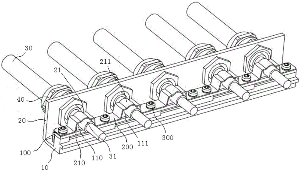
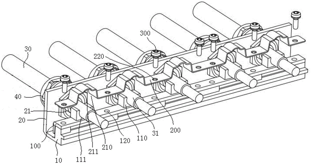
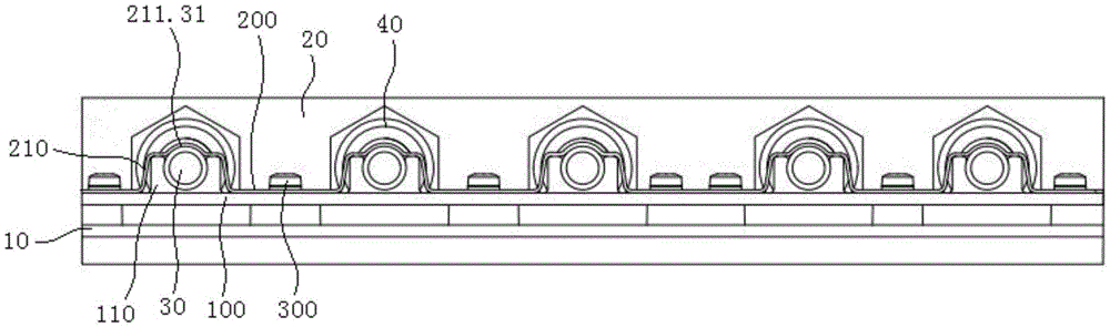
[0019] see Figure 1 to Figure 4 , shown in the figure is a quick press-fit electromagnetic shielding structure for cables, including a lower pressing plate 100 and an upper pressing plate 200 .

[0020] The lower pressing plate 100 is fixedly arranged on the shell mounting seat 10 of the motor controller, and five wiring seats 110 are arranged at intervals along the length direction on the lower pressing plate 100, and the incoming lines of the five wiring seats 110 and the housing 20 of the motor controller The holes 21 are in a one-to-one correspondence. Of course, the number of wire sockets 110 is not limited to the number in this embodiment, and it should be determined according to the number of wire inlet holes in the casing of the specifi...


PUM


Abstract

The invention discloses an electromagnetic shielding structure for quick pressed cables. The electromagnetic shielding structure comprises a lower pressing plate and an upper pressing plate. The lower pressing plate is arranged on a housing mounting seat of a motor controller. The lower pressing plate is provided with a plurality of junction blocks which are separately arranged in the length direction and are in one-to-one correspondence with wire inlet holes of the housing of the motor controller. Each junction block is provided with a wiring groove which is used for embedding a metal shielding layer of the cable. The upper pressing plate detachably presses the lower pressing plate and compresses the metal shielding layer of the cable which is arranged in each wiring groove of the lower pressing plate. The electromagnetic shielding structure has beneficial effects of quickly pressing and fixing one or a plurality of cables on the housing of the motor controller, ensuring electromagnetic compatibility, greatly reducing cost of a connector, and preventing metal shielding layer damage in detachment of the cables for maintenance.

Description

technical field [0001] The invention relates to the technical field of cable electromagnetic shielding, in particular to an electromagnetic shielding structure for fast press-fit cables. Background technique [0002] The maturation of the electric vehicle industry requires higher and higher integration of its electric drive system. At the same time, the motor controller, one of the three major components of electric vehicles, is developing in the direction of high power density and high-speed signal transmission. The electromagnetic compatibility (EMC) problem of the control system that comes from it is becoming more and more prominent. As the cables connecting each module in the electronic control system, they can receive electromagnetic waves and radiate electromagnetic waves. Therefore, cables are not only a good channel for conduction interference, but also an important source of radiation interference. How to solve the electromagnetic compatibility problem of the cable...

Claims


Application Information

Patent Timeline
IPC IPC(8): H01R13/516H01R13/6581
CPCH01R13/6581H01R13/516
Inventor 应忠良马彪王云刚
Owner CHUANGQU SHANGHAI NEW ENERGY TECH CO LTD
Why Eureka
Try Eureka