Reciprocating rotation excitation stand system

A bench system and excitation system technology, applied in the field of testing of rotary actuators and their vibration control systems, can solve problems such as single test results, impossibility of testing, poor applicability, etc., to ensure stable operation, prevent excessive vibration, The effect of large carrying capacity

Active Publication Date: 2016-04-13
合肥庐阳科技创新集团有限公司
View PDF5 Cites 4 Cited by
  • Summary
  • Abstract
  • Description
  • Claims
  • Application Information

AI Technical Summary

Problems solved by technology

However, it can only provide a single positive or reverse rotation excitation, which makes it impossible to test various limited-angle rotary actuators. It is even more difficult to test high-torque limited-angle rotary actuators, which eventually leads to system test results. Single defect with relatively poor applicability
[0003] In addition, the rotary excitation bench in the prior art cannot complete the performance test of the vibration control system based on rotary passive / active / semi-active actuators

Method used


Image

  • Reciprocating rotation excitation stand system
  • Reciprocating rotation excitation stand system
  • Reciprocating rotation excitation stand system

Examples


Embodiment 1

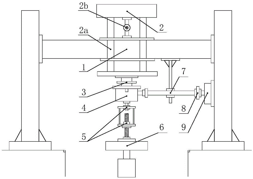
[0053] Embodiment 1: The structure of the reciprocating rotary excitation bench system in this embodiment is set as follows:

[0054] The gantry 1 is composed of columns on both sides and the top horizontal beam connected between the columns on both sides; the mass block guide platform 2 is arranged on the horizontal beam, and the mass block guide platform 2 is supported by the horizontal beam, and can move along the vertical guide column 2a lifting, a limit rod 2b is set between the top table of the mass guide table 2 and the horizontal beam, the bottom table of the quality block guide table 2 is located below the horizontal beam; The vibration control module 3, the bottom surface of the vibration control module 3 is rigidly connected with the direction changing torsion increasing device 4.

[0055] The input shaft of the direction-changing torsion-increasing device 4 is vertically downward, and is connected with the motion conversion device 5 located at the bottom of the dir...

Embodiment 2

[0075] Embodiment 2: The structure of the reciprocating rotary excitation bench system in this embodiment is set as follows:

[0076] see Figure 5 , the gantry 1 is composed of columns on both sides and the top horizontal beam connected between the columns on both sides; the mass guide platform 2 is arranged on the horizontal beam, and the mass guide platform 2 is supported by the horizontal beam, and can be guided vertically The column 2a is free to lift, and the bottom surface of the mass guide platform 2 is located below the horizontal beam; the vibration control module 3 is set on the bottom surface of the bottom surface of the mass guide platform 2, and the bottom surface of the vibration control module 3 is executed with a limited rotation angle of large torque. The housing of the device 9 is rigidly connected.

[0077] The rotating shaft of the high-torque limited-angle actuator 9 is vertically downward, and is connected with the output shaft of the reducer 10 located...


PUM


Abstract

The invention discloses a reciprocating rotation excitation stand system which is characterized in that a reciprocating rotation excitation system is composed of a linear actuating vibration table, a motion conversion device, and a turning torque rising device, the motion conversion device converts the vertical reciprocating linear excitation formed by the linear actuating vibration table into vertical reciprocating rotation excitation, the turning torque rising device converts the vertical reciprocating rotation excitation into horizontal reciprocating rotation excitation, the torque and the rotation travelling of the horizontal reciprocating rotation excitation can be increased and reduced in the turning torque rising device, and an excitation control module measures the vibration amplitude and the linear exciting force of the reciprocating rotation excitation system at the same time. The reciprocating rotation excitation stand system is suitable for the characteristic test of a large-torque limited angle actuator and can perform the vibration control experiment test based on passive / active / half-active rotary actuator.

Description

technical field [0001] The invention relates to the technical field of testing a rotary actuator and its vibration control system, in particular to a reciprocating rotary excitation system for a reciprocating rotary actuator. Background technique [0002] There are many types of testing instruments for rotary actuators, such as torque wrenches and torque meters. Torque wrench is a kind of wrench with adjustable torque, pre-adjust the torque, and then tighten the object. Using this feature, it can be used as the most simple and practical rotating excitation tool or torque testing instrument, but the accuracy of this instrument is low , The rotary excitation that can be applied is small and the range is very limited. The torque meter is an accurate measurement instrument for the tightness of the lids of various containers such as medical equipment, cosmetics and beverages, the tightness of screws, the torque of valve opening and closing, and various torques. It is also widely...

Claims


Application Information

Patent Timeline
IPC IPC(8): G01M13/02
CPCG01M13/025
Inventor 白先旭邹祺沈升钱立军
Owner 合肥庐阳科技创新集团有限公司
Why Eureka
Try Eureka