
Two-way automatic locking device in the tube

An automatic locking and locking mechanism technology, which is applied to the connection of rods, connecting components, mechanical equipment, etc., can solve the problems of locking device detachment, locking failure, etc., achieve a firm locked state and increase the locking force , easy adjustment and stable effect

Active Publication Date: 2018-02-16
陈建丰
View PDF6 Cites 2 Cited by
  • Summary
  • Abstract
  • Description
  • Claims
  • Application Information

AI Technical Summary

Problems solved by technology

[0003] The purpose of the present invention is to provide a two-way automatic locking device to solve the problem that the one-way automatic locking device in the prior art is locked by a one-way locking force. The inner wall of the tube is detached, resulting in technical problems of locking failure

Method used


Image

  • Two-way automatic locking device in the tube
  • Two-way automatic locking device in the tube
  • Two-way automatic locking device in the tube

Examples


Embodiment 1

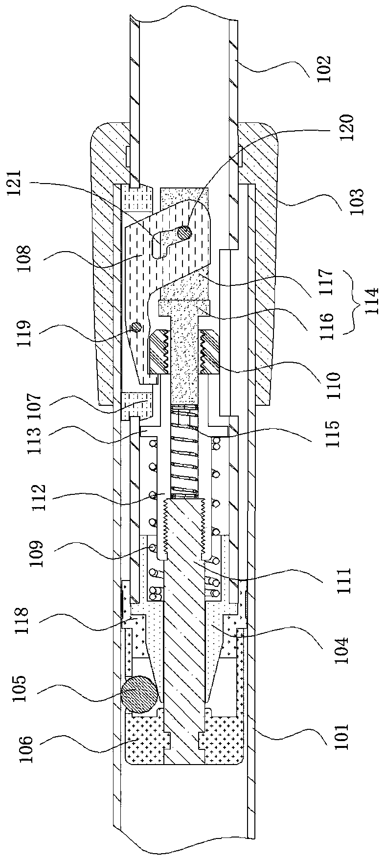
[0034] Such as figure 2 As shown, in a normal state, the bidirectional automatic locking device in the tube provided by the first embodiment is in a locked state, and the bidirectional automatic locking device in the tube includes an outer tube 101, an inner tube 102, a first locking mechanism and a second locking mechanism. Locking mechanism; the inner tube 102 is arranged inside the outer tube 101; the first locking mechanism includes a tapered sleeve 104, a slider and a friction control assembly. In this embodiment, the slider is The ball 105, the tapered sleeve 104 is arranged at the end of the inner tube 102, the friction control assembly is used to make the ball 105 move radially along the tapered surface of the tapered sleeve 104, so that the The ball 105 abuts against the inner wall of the outer tube 101 ; the second locking mechanism is used to prevent the ball 105 from breaking away from the inner wall of the outer tube 101 . In this embodiment, the number of the b...

Embodiment 2

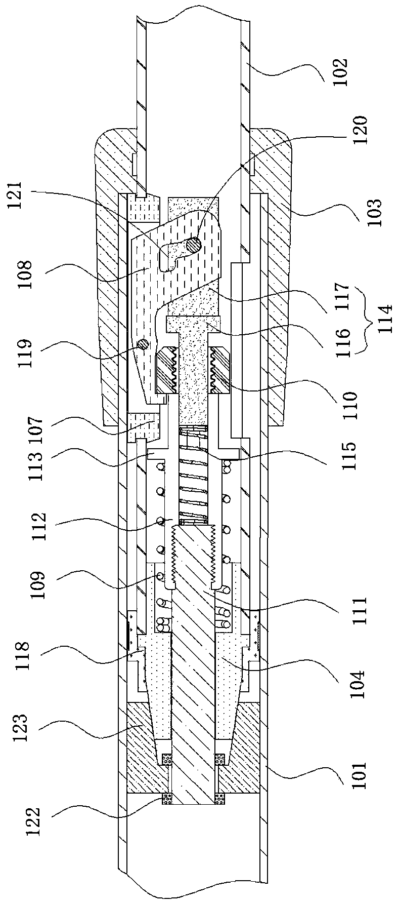
[0043] Combine below image 3 Embodiment 2 is described. The same components use the same reference numerals as in the first embodiment, and reference is made to the description of the first embodiment. The difference from Embodiment 1 is that the limiting member used in this embodiment is a bracket 122, and the sliding member used is a locking block 123. The number of the locking blocks 123 is multiple, and the locking block Block 123 is provided with a wedge-shaped surface that cooperates with the tapered surface of said tapered sleeve 104 .

[0044] The unlocking and locking movement process of the in-pipe bidirectional automatic locking device provided in this embodiment is as follows:

[0045] Unlocking process: such as image 3 As shown, a leftward external force is applied to the end of the second rod part 117, the second rod part 117 and the first rod part 116 move to the left together, the elastic member 115 is compressed, and at the same time drives The second sh...


PUM


Abstract

The invention relates to the technical field of telescopic systems and in particular to an intra-pipe bi-directional automatic locking device. The intra-pipe bi-directional automatic locking device comprises an outer pipe, an inner pipe, a first locking mechanism and a second locking mechanism. The inner pipe is arranged in the outer pipe. The first locking mechanism comprises sliding pieces, a tapered sleeve and a friction control assembly. The tapered sleeve is arranged at the end of the inner pipe. The friction control assembly is used for making the sliding pieces move in the radial direction along the tapered surface of the tapered sleeve so that the sliding pieces can abut against the inner wall of the outer pipe. The second locking mechanism is used for preventing the sliding pieces from being separated from the inner wall of the outer pipe. According to the intra-pipe bi-directional automatic locking device, the first locking mechanism and the second locking mechanism are arranged, so that the outer pipe and the inner pipe can be locked bi-directionally, on the one hand, connection between the inner pipe and the outer pipe is more steady, and on the other hand, the inner pipe and the outer pipe can be adjusted more conveniently in the telescopic length direction.

Description

technical field [0001] The invention relates to the technical field of telescopic systems, in particular to a bidirectional automatic locking device in a pipe. Background technique [0002] The telescopic tube changes its length through the relative movement between the inner and outer tubes, and can be stretched or shortened according to needs, which is convenient to carry and reduces weight, and has been widely used in tools of various lengths. In order to facilitate the adjustment of the telescopic tube in the length direction, a locking device is often provided inside the tube. The existing locking devices are usually mechanical locking devices such as buckle type, rotating leg type and round nut type on the rotating leg. , when this type of locking device is used to adjust the length of the telescopic tube again, it is necessary to change the working state of the original telescopic tube, and then restore the original working state of the telescopic tube after manual ad...

Claims


Application Information

Patent Timeline
Patent Type & Authority Patents(China)
IPC IPC(8): F16B7/14
CPCF16B7/1409
Inventor 陈建丰
Owner 陈建丰
Learn More