Shockproof device for electronic element bearing plate

A technology for electronic components and shock-proof devices, which is applied to the circuit layout and other directions on the support structure, can solve problems such as damage to the carrier board

Inactive Publication Date: 2016-04-06
CHONGQING CHENGSHUO TECH
View PDF0 Cites 1 Cited by
  • Summary
  • Abstract
  • Description
  • Claims
  • Application Information

AI Technical Summary

Problems solved by technology

[0003] The present invention intends to provide an anti-vibration device for the electronic component bearing board to solve the problem that the existing bearing board is easily damaged by the vibration generated by the machine body

Method used


Image

  • Shockproof device for electronic element bearing plate
  • Shockproof device for electronic element bearing plate

Examples


Embodiment Construction

[0010] The present invention will be described in further detail below by means of specific embodiments:

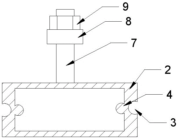
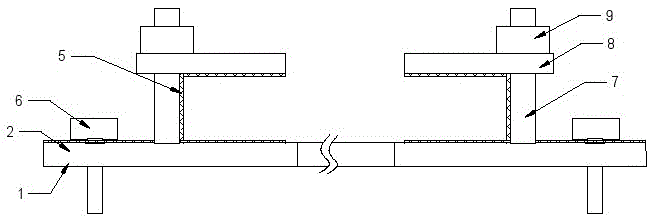
[0011] The reference signs in the drawings of the description include: fixed plate 1 , connector 2 , slideway 3 , ball 4 , elastic layer 5 , fastening bolt 6 , fastener 7 , pressure plate 8 , and nut 9 .

[0012] The embodiment is basically as attached figure 1 , figure 2 Shown: the anti-vibration device of the electronic component bearing plate includes a fixing mechanism and two fastening mechanisms. Slideways 3 are provided on the outer sidewalls, baffles are installed at both ends of the slideways 3, and balls 4 are provided on both inner sidewalls corresponding to the connector 2. During assembly, the ball 4 of one connecting piece 2 is slidably connected in the slideway 3 of the other connecting piece 2, thus forming a telescopic fixed plate 1, and on the two left and right connecting pieces 2 at the outermost edge of the fixed plate 1 Connecting holes are respe...


PUM


Abstract

The invention discloses a shockproof device for an electronic element bearing plate, and the device comprises a fixing mechanism and two fastening mechanisms. The fixing mechanism comprises a fixing plate, and the fixing plate is provided with a chute. Moreover, two ends of the fixing plate are respectively provided with a connection hole, and the connection holes are movably connected with fastening bolts. The fixed plate consists of a plurality of hollow connection parts, and outer side walls of the connection part are provided with slideways. Two ends of each slideway are provided with baffle plates, and an inner side wall of each connection part is provided with a rolling ball. The rolling ball of one connection part is slidingly connected in the chute of the adjacent connection part. Each fastening mechanism comprises a fastening part which is fixedly installed on the fixing plate, and a pressure plate which is movably connected to the fastening part. The fastening parts are in threaded connection with screw caps which are used for limiting the pressure plates. The screw caps are located above the pressure plates, and the surfaces, contacting with the bearing plate, of the fastening mechanisms and the fixing plates are respectively provided with elastic layers. According to the technical scheme of the invention, the device solves a problem that a conventional bearing plate is liable to be damaged by the vibration caused by a machine body.

Description

technical field [0001] The invention relates to auxiliary equipment for installing electronic components, in particular to an anti-vibration device for a carrying plate of electronic components. Background technique [0002] The load board is a kind of bearing of the circuit, which is covered with countless lines. It is convenient to connect the various components, and it is easy to make and replace the components. Therefore, the stability and durability of the load board determine the service life of the electronic product. The load board Most of them are fixed on the body by passing bolts through the mounting holes on the load plate. The pure hardware connection between the load plate and the body, the electronic components on the load plate are easy to loosen under long-term vibration and cause breakage between components, especially In industrial control, military industry, aerospace and other fields, encountering harsh vibration environments, there is no guarantee for t...

Claims


Application Information

Patent Timeline
Patent Type & Authority Applications(China)
IPC IPC(8): H05K7/02
Inventor 陈佳英
Owner CHONGQING CHENGSHUO TECH
Why Eureka
Try Eureka