
Bionic electronic image stabilization method and device based on vestibular reflex mechanism

An electronic image stabilization and vestibular reflex technology, applied in the field of image processing, can solve problems such as time-consuming, poor real-time performance, and poor stability.

Active Publication Date: 2017-03-29
COMP APPL TECH INST OF CHINA NORTH IND GRP
View PDF8 Cites 0 Cited by
  • Summary
  • Abstract
  • Description
  • Claims
  • Application Information

AI Technical Summary

Problems solved by technology

However, the current bionic electronic image stabilization algorithm based on the vestibulo-oculomotor reflex mechanism of human-like eyeballs has poor stability, time-consuming, and poor real-time performance.

Method used


Image

  • Bionic electronic image stabilization method and device based on vestibular reflex mechanism
  • Bionic electronic image stabilization method and device based on vestibular reflex mechanism
  • Bionic electronic image stabilization method and device based on vestibular reflex mechanism

Examples


Embodiment 1

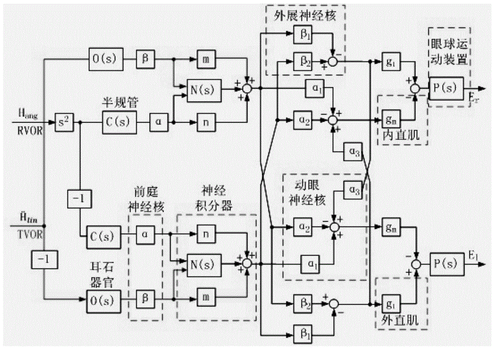
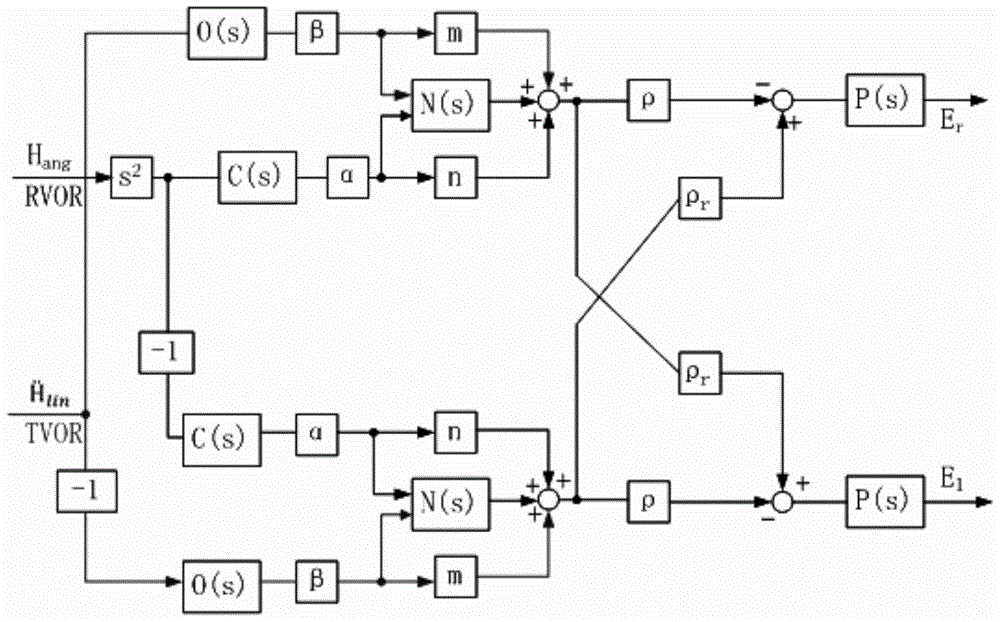
[0062] Example 1, such as Figure 4 As shown, a bionic electronic image stabilization method based on the vestibular reflection mechanism of the embodiment of the present invention, the method includes:

[0063] Step 1, the binocular vision system adopted simulates the binocular VOR of the human eye, the first camera simulates the VOR of the left eye, and the second camera simulates the VOR of the right eye;

[0064] Step 2, the first motor is connected to the first camera, the FPGA board measures the sudden change in current of the first motor to obtain the rotational acceleration of the first camera, the second motor is connected to the second camera, and the FPGA board measures the sudden change in current of the second motor , to get the rotational acceleration of the second camera;

[0065] Step 3, the first strain gauge force sensor is connected to the first camera, the FPGA board measures the strain of the first strain gauge force sensor to obtain the translational acc...

Embodiment 2

[0084] Example 2, such as Figure 5 As shown, the present invention also provides a bionic electronic image stabilization device based on the vestibular reflex mechanism, including:

[0085] A first camera, which is connected to a first motor, the first camera simulates the vestibulo-oculomotor reflex of the left eye, and the first motor simulates the rotational movement of the first camera;

[0086] A second camera, which is connected with a second motor, the second camera simulates the vestibulo-oculomotor reflex of the right eye, and the second motor simulates the rotational movement of the second camera;

[0087] a first strain gauge force sensor, which is connected to the first motor, and the first strain gauge force sensor simulates the translational movement of the first camera;

[0088] a second strain gauge force sensor, which is connected to the second motor, and the second strain gauge force sensor simulates the translational movement of the second camera;

[0089...


PUM


Abstract

The invention discloses a bionic electronic image stabilizing method based on the vestibular reflection mechanism. The method comprises steps that, vestibulo-ocular reflection of the left eye and the right eye is simulated by two cameras; abrupt current change of a first motor and a second motor is measured by an FPGA board card to acquire a rotation acceleration of the two cameras; strain of a first strain gage force sensor and a second strain gage force sensor to acquire a translation acceleration of the two cameras; the rotation acceleration and the translation acceleration are fed back to an image stabilizing decision unit; matching motion estimation on previous / later frames of images shot by the two cameras is carried out by the FPGA board card, and the matching motion result is fed back to an image stabilizing decision unit; through an image stabilizing algorithm, the rotation speed and the rotation direction of the two cameras for compensation motion are acquired and are sent to a servo control unit, motion of the two cameras is controlled, and image stabilizing is realized. The method is advantaged in that, the image stabilizing algorithm is realized through FPGA, good stability is realized, vision errors caused by self rotation or translation of the cameras are eliminated, and the method further has advantages of high efficiency, short consumption time and good timeliness.

Description

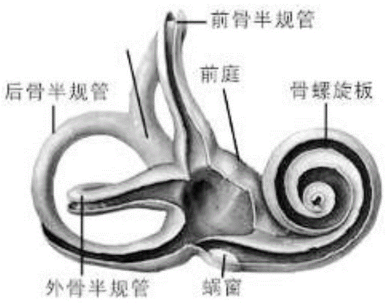
technical field [0001] The invention relates to the technical field of image processing, in particular to a bionic electronic image stabilization method and device based on a vestibular reflection mechanism. Background technique [0002] The vestibular organ of the inner ear is the balance receptor of the human body, which includes three pairs of semicircular canals and the elliptical sac and balloon of the vestibule. anatomy of inner ear vestibule figure 1 As shown, there are crests of the pot in the semicircular canal, and otoliths (also known as sac spots) in the elliptical sac. They are all vestibular terminal receptors, which can sense the stimulation of various specific motion states. The semicircular canal senses angular plus (decrease) speed motion stimulation, while the ellipse and the sac spot of the sac feel the change of horizontal or vertical straight line plus (minus) speed. When the vehicle we take rotates or turns (such as a car turning, an airplane making ...

Claims


Application Information

Patent Timeline
Patent Type & Authority Patents(China)
IPC IPC(8): H04N13/02G06T7/20
CPCG06T7/20G06T2207/10016H04N13/246
Inventor 赵小川刘培志陈晓鹏孔小梅施建昌张敏徐鹏王宁高路
Owner COMP APPL TECH INST OF CHINA NORTH IND GRP
Learn More