
Insulation cylinder and transformer

A technology for transformers and insulating cylinders, applied in the field of transformers, can solve the problems of high requirements on dimensional tolerance accuracy, difficult assembly, inconvenient installation of spacers, etc., and achieves the effects of shortening assembly time, facilitating single-person operation, and achieving significant economic effects.

Active Publication Date: 2018-06-15
WOLONG ELECTRIC GRP CO LTD +1
View PDF7 Cites 1 Cited by
  • Summary
  • Abstract
  • Description
  • Claims
  • Application Information

AI Technical Summary

Problems solved by technology

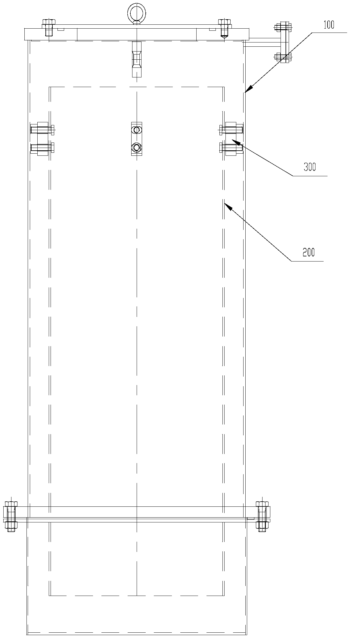
[0003] The existing problems are as follows: 1. The spacer is inconvenient to install, the operability is poor, and more than 2 operators are required, the working hours are long, and the labor cost is high; 2. Since the spacer is placed by backhand groping, there must be a gap between the insulating cylinder and the raised seat. Sufficient distance is reserved, and there are high requirements for the dimensional tolerance accuracy of spacers and insulating cylinders. If they are out of tolerance, assembly is difficult; 3. Since the insulating cylinder is placed in the air in the raised seat, there is no Positioning, so before installing the insulating cylinder, it is necessary to manually climb into the hole in the rising seat, and a stay limit should be placed between the insulating cylinder and the rising seat to prevent damage to the insulating cylinder. This operation is laborious and material-intensive (the stay It will lose its effect after the end of the limit); 4. The rising seat must be protected before it stands up, so as to avoid the part of the insulating cylinder beyond the rising seat from being bumped and damaged, which increases the workload; Workers enter its interior, time-consuming and labor-intensive

Method used


Image

  • Insulation cylinder and transformer
  • Insulation cylinder and transformer
  • Insulation cylinder and transformer

Examples


Embodiment Construction

[0024] In order to enable those skilled in the art to better understand the solutions of the present invention, the technical solutions in the embodiments of the present invention will be clearly and completely described below in conjunction with the drawings in the embodiments of the present invention.

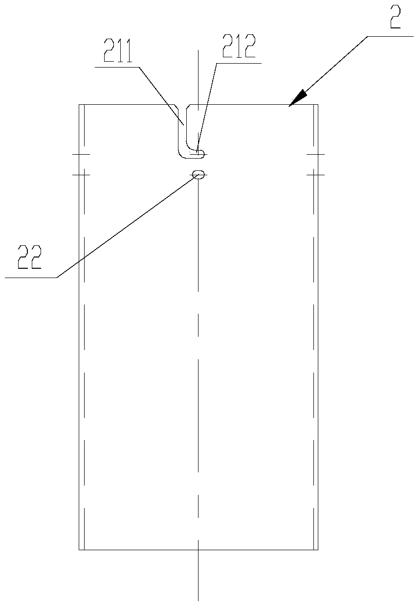
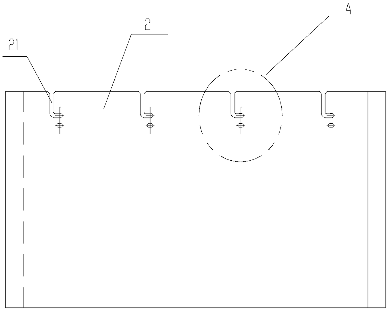
[0025] Such as Figure 2-7 As shown, an insulating cylinder and a transformer provided by the present invention include: a riser 1 , an insulating cylinder 2 , a spacer 3 and a fixing assembly 4 . The insulation cylinder 2 includes an insulation cylinder with a hollow interior, and the upper end of the side wall of the insulation cylinder has four open slots 21, each of which includes a vertical portion 211 and a limiting portion 212 obliquely intersecting with the vertical portion 211, and One end of the vertical part 211 extends to the upper surface of the insulating cylinder; the spacer 3 is provided with a through hole 31; the fixing assembly 4 includes a first insulating...


PUM


Abstract

The invention discloses an insulating cylinder and a transformer. The insulating cylinder comprises a hollow insulating cylinder body, wherein the upper end of the insulating cylinder body is provided with at least two open grooves, each open groove comprises a vertical part and a limiting part which obliquely intersects with the vertical part, and one end of each vertical part extends to the end face of the insulating cylinder body. By changing the structure of the insulating cylinder and a cushion block, the cushion block is made to penetrate through the vertical part and the limiting part of each open groove through an insulating threaded rod and fixed to an ascending flanged base through a first insulating nut, and the insulating cylinder and the ascending flanged base are fixed through a second insulating nut. Operation by a single person is convenient, working time is saved, time for assembly of the ascending flanged base and the insulating cylinder is greatly shortened, and the economic effect is remarkable.

Description

technical field [0001] The invention relates to the field of transformers, in particular to an insulating cylinder and a transformer. Background technique [0002] The schematic diagram of the assembly of the existing raised seat 100 and the insulating cylinder, such as figure 1 , directly fix the insulating cylinder through insulating bolts, the main function of the insulating cylinder is to divide the oil gap between the bushing and the wall of the raised seat, increase the insulation distance, and reduce the diameter of the raised seat. The parts are composed of insulating cylinder 200, insulating pad 300 and insulating bolts (. The insulating cylinder is fixed on the inner wall bottom plate of the raised seat by twisting the insulating bolts. [0003] The existing problems are as follows: 1. The spacer is inconvenient to install, the operability is poor, and more than 2 operators are required, the working hours are long, and the labor cost is high; 2. Since the spacer i...

Claims


Application Information

Patent Timeline
Patent Type & Authority Patents(China)
IPC IPC(8): H01F27/32
CPCH01F27/325
Inventor 柏广洲于春梅孙长山魏喜柱王伟
Owner WOLONG ELECTRIC GRP CO LTD
Learn More