A Deformed Speckle Generation Method Based on Reverse Mapping Method
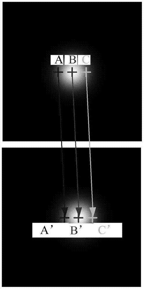
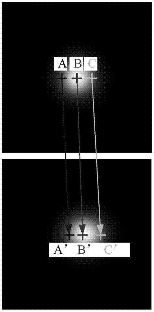
A technology of reverse mapping and speckle, applied in image generation, image data processing, filling plane with attributes, etc., can solve the problems of large system error, complex generation method, difficult programming and implementation, etc. Effects that are easy to program
- Summary
- Abstract
- Description
- Claims
- Application Information
AI Technical Summary
Problems solved by technology
Method used
Image
Examples
Embodiment 1
[0093] Example 1: Rigid body translation
[0094] The reference image is a randomly generated speckle image with a resolution of 256 × 256 pixels, the number of speckle grains is 2000, and the speckle grain radius is 4. Using the original method and the reverse mapping method, a total of 20 translation images with an interval of 0.05 pixels are generated along the x direction, that is, the displacement of the image sequence is 0-1 pixel. The parameters and variables in the DIC calculation are selected to be consistent, the two groups of speckle images are analyzed, and the error and standard deviation of the displacement field are calculated, which are expressed as follows:
[0095]
[0096] in, Represents the average value of all calculated point displacements in the same graph, namely v true represents the theoretical deformation parameter; N represents the number of all calculation points.
[0097] from Figure 5It can be seen that the maximum error of the displac...
Embodiment 2
[0098] Example 2: Uniform deformation
[0099] With reference to the speckle image unchanged, the original method and the reverse mapping method are used to generate a uniform stretch map along the y-direction, respectively. Analyze the two sets of speckle images, regard v in formula (10) as the strain, and calculate the error and standard deviation of the strain field. The results are as follows Figure 7 , Figure 8 , Figure 9 and Figure 10 shown.
[0100] For the deformation in the x-direction, when the microstrain is less than 10000, the calculation errors of the speckle images generated by the two methods are similar, while when the microstrain is greater than 10000, the error based on the original method increases almost linearly, while the calculation based on the reverse mapping method There is no significant change in error, and the maximum strain error does not exceed 50 microstrain. from Figure 8 It is found that the standard deviation of the calculated str...
Embodiment 3
[0102] Example 3: Non-uniform deformation
[0103] The reference image is a randomly generated speckle image with a resolution of 500 × 500 pixels, the number of speckle particles is 4000, and the radius of the speckle particles is 4. The original method and the reverse mapping method are used to generate non-uniform deformation maps along the y direction, respectively. The displacement field in the y direction conforms to the sin distribution, that is, v=Asin(2πy / T), A=1, T=200.
[0104] from Figure 11 It can be seen that on the whole, the error of the speckle map generated based on the original method is relatively large, and the maximum deviation can reach 2000 microstrains. And the error distribution law of the latter is more realistic, that is, the error is the largest at the peak of strain. Compared Figure 12 It can be seen that the standard deviations calculated based on the two kinds of speckles are not much different, and the maximum is less than 300 microstrains...
PUM
 Abstract
Description
Claims
Application Information
 - R&D
- Intellectual Property
- Life Sciences
- Materials
- Tech Scout
- Unparalleled Data Quality
- Higher Quality Content
- 60% Fewer Hallucinations
Browse by: Latest US Patents, China's latest patents, Technical Efficacy Thesaurus, Application Domain, Technology Topic, Popular Technical Reports.
© 2025 PatSnap. All rights reserved.Legal|Privacy policy|Modern Slavery Act Transparency Statement|Sitemap|About US| Contact US: help@patsnap.com


