An air conditioner outdoor unit tray

A technology for air-conditioning outdoor units and trays, which is applied in air-conditioning systems, space heating and ventilation, and space heating and ventilation details. The effect of high sum height

Active Publication Date: 2018-10-26
GREE ELECTRIC APPLIANCES INC OF ZHUHAI
View PDF8 Cites 0 Cited by
  • Summary
  • Abstract
  • Description
  • Claims
  • Application Information

AI Technical Summary

Problems solved by technology

[0013] The purpose of the present invention is to provide a tray for an outdoor unit of an air conditioner, which solves the problems that the crossbeam of the "Chuan" tray is easy to be crooked, easy to fall off, the flaps of the clamping operation are easy to break, and the clamping is unstable, and the production of the "I"-shaped tray is burnt. The problem of high friction during welding rotation

Method used


Image

  • An air conditioner outdoor unit tray
  • An air conditioner outdoor unit tray
  • An air conditioner outdoor unit tray

Examples


Embodiment 1

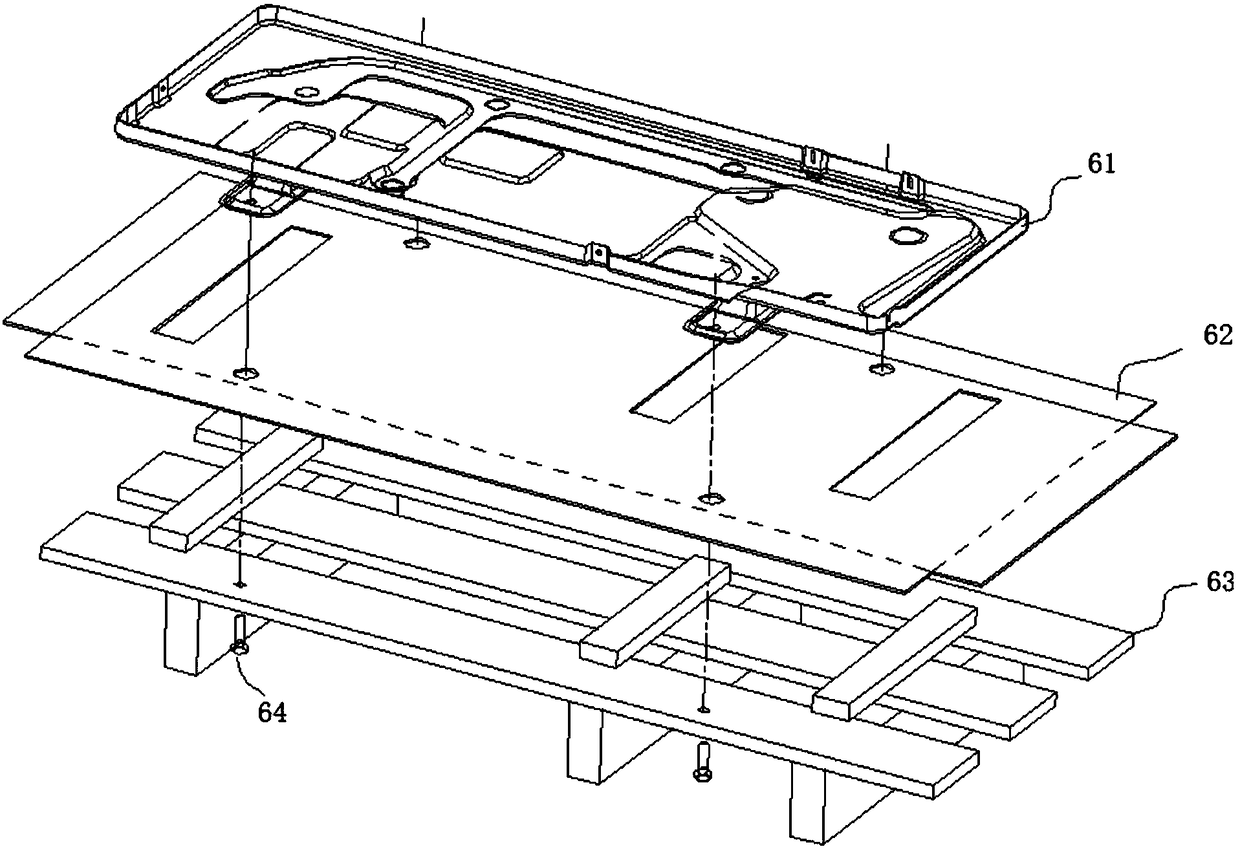
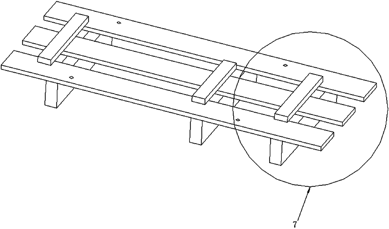
[0050] Such as Figure 8 As shown, an embodiment of the present invention provides an air conditioner outdoor unit tray, which generally includes a sleeper 1 , an upper plank 2 , a beam 3 and a lower plank 4 . The crossties 1 are placed on the upper plank 2 . The beam 3 is used to support the upper deck 2 , which includes a first set of beams 31 and a second set of beams 32 respectively arranged under the upper deck 2 and located at both ends of the upper deck 2 . The lower deck 4 comprises a first lower deck 41 and a second lower deck 42, the first lower deck 41 is connected to the lower end of the first set of beams 31; the second lower deck 42 is connected to the lower end of the second set of beams 32; the first lower deck 41 and the lower end of the second set of beams 32; The gap between the second lower decks 42 is not smaller than the fork width of the forklift.

[0051] The air-conditioning outdoor unit tray described in this embodiment combines the characteristics ...

Embodiment 2

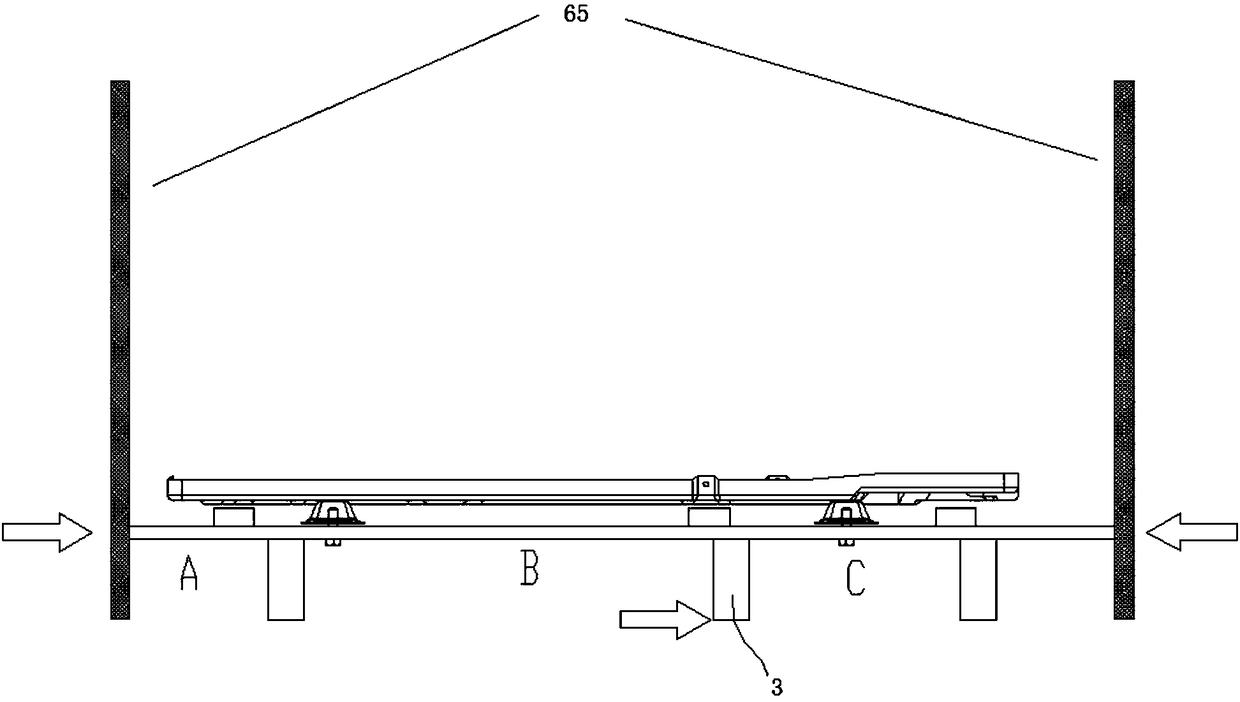
[0060] The air conditioner outdoor unit tray provided by another embodiment of the present invention is as follows: Figure 11 , Figure 12 , Figure 13 shown in . In order to facilitate the use of forklifts, organic foot fixing holes 5 are arranged on the upper deck. The machine foot fixing hole 5 is located between the second beam 312 and the third beam 321 . The air-conditioning outdoor unit tray of this design has a relatively large distance between the second beam 312 and the third beam 321, that is, the width of the passage for the fork of the forklift to pass through is wider, and the use of the fork is more convenient. At the same time, due to the increase of the width, The requirement for the strength of the upper deck also increases accordingly, and the method of increasing the strength of the upper deck can be achieved by increasing the strength of the upper deck material or by using a double-layer upper deck, as described in the following examples.

[0061] In ...


PUM


Abstract

The invention discloses an air-conditioning outdoor unit tray. The air-conditioning outdoor unit tray comprises a sleeper, an upper plank, cross beams and lower planks; the sleeper is disposed on the upper plank; the cross beams are used for supporting the upper plank, and include a first group of cross beams and a second group of cross beams which are arranged below the upper plank and located at two ends of the upper planks, respectively; the lower planks include a first lower plank and a second lower plank, the two of which are connected to lower ends of the first and second groups of cross beams, respectively; the air-conditioning outdoor unit tray of the present invention solves the problems of easy tilting and easy dropping of III-shaped tray cross beams, the problem of large frictional force of an H-shaped tray during welding rotation in production, and also the problem of separation of the lower planks due to the lower planks may be pressed by a forklift wheel easily; further, the air-conditioning outdoor unit tray solves the problems of easy tilting and easy dropping of the III-shaped tray cross beams, easy breakage of a wing plate during a clamping operation and unstable clamping; meanwhile, as the lower planks designed to be disconnected from each other, the total height of the cross beams and the lower planks is great to facilitate forking of a forklift.

Description

technical field [0001] The invention relates to an air conditioner outdoor unit tray, which belongs to the technical field of air conditioner production and installation. Background technique [0002] The outdoor unit of the air conditioner, especially the outdoor unit with a large power of 5P and above, can weigh more than 100kg and is not suitable for manual handling. Usually, a pallet is used to fix the base, and then a motorized forklift, manual hydraulic forklift, clamping truck, etc. transport. Such as figure 1 As shown, the assembly method of the chassis 61 of the outdoor unit and the tray 63 is to put a piece of cardboard or foam pad 62 on the tray to protect against dust, and the feet of the chassis 61 of the outdoor unit pass through the cardboard or foam pad 62 It is fixed on the pallet 63 with bolts 64 . After fixing the chassis of the outdoor unit, the following production operations are carried out, that is, the tray 63 is initially produced along with the o...

Claims


Application Information

Patent Timeline
IPC IPC(8): F24F1/60F24F13/32
CPCF24F1/60F24F13/32
Inventor 梁燕飞黄胜文李游陈洪凯庞有超
Owner GREE ELECTRIC APPLIANCES INC OF ZHUHAI
Why Eureka
Try Eureka