
Building guard railing

A technology of guardrail and guardrail body, which is applied to buildings, building structures, railings, etc., can solve the problems of affecting aesthetics, cannot be reused, inconvenient for transportation and installation, etc., and achieves convenient transportation, firm installation, and convenient relative. moving effect

Inactive Publication Date: 2016-04-06
重庆市合川区盐井工程建筑有限公司
View PDF9 Cites 3 Cited by
  • Summary
  • Abstract
  • Description
  • Claims
  • Application Information

AI Technical Summary

Problems solved by technology

[0002] Existing protective fences on exterior walls of buildings are usually integrally welded structures, and are fixed on the exterior walls of buildings by welding, which is inconvenient for transportation and installation. At the same time, after some parts are damaged, they cannot be used again, and the way of welding is used, which seriously affects its aesthetics

Method used


Image

  • Building guard railing

Examples


Embodiment 1

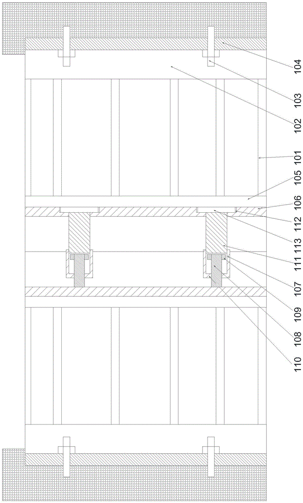
[0021] Such as figure 1 As shown, a building guardrail includes at least two interconnected guardrail bodies 101, and a fixing device is provided on one side of the guardrail body 101 located at the edge, and the fixing device includes embedded bolts 103 The fixed plate 102 fixedly connected to the building exterior wall is provided with a stepped groove 104 on one side of the fixed plate 102, and the stepped groove 104 is arranged along the length direction of the fixed plate 102. The embedded bolts 103 runs through the side wall of the stepped groove 104 and is fixedly connected to the inner side of the stepped groove 104 by nuts, and fixed ends 105 are respectively arranged on the adjacent guardrail body 101, and the fixed ends 105 and the fixed plate 102 are parallel to each other, fixed flanges 106 are respectively arranged in the middle of the same side of the fixed end 105, and the fixed flanges 106 are respectively arranged along the length direction of the fixed end 1...

Embodiment 2

[0024] In this embodiment, on the basis of Embodiment 1, in order to facilitate the installation of the limiting part, in this embodiment, preferably, the end of the connecting sleeve 108 away from the fixing flange 106 is provided with an external thread, The limiting portion 109 is threadedly connected to the connecting sleeve 108 .

[0025] In order to facilitate the installation of the fixing rod, in this embodiment, preferably, a threaded hole is provided on the fixing flange 106 for installing the fixing rod 111, and the fixing rod 111 is screwed to the fixing rod 111. on the flange 106.

[0026] In order to make the structure of the fixed rod more stable and facilitate its installation, in this embodiment, preferably, a counterbore 112 is provided on the fixed flange 106 for installing the fixed rod 111, and a counterbore 112 is provided on the fixed rod 111. 111 is provided with a hexagon nut 113 at the end away from the connecting sleeve 108 , and the hexagon nut 113...


PUM


Abstract

The invention discloses a building guard railing. The building guard railing comprises at least two guard railing bodies connected with each other. A fixing device is arranged on one side of the guard railing body located at the edge. The fixing device comprises a fixing board which is fixedly connected to a building exterior wall through pre-embedded bolts. One side of the fixing board is provided with stepped grooves. The pre-embedded bolts penetrate the side walls of the stepped grooves and are fixedly connected to the inner sides of the stepped grooves through nuts. The adjacent guard railing bodies are respectively provided with a fixing end portion. A fixing flange is arranged on the middle portion on the same side of each fixing end portion. Through the splicing of the guard railing bodies, the size of the guard railing is decreased, so that the guard railing is convenient to transport and install. Furthermore, all connecting structures are arranged on the same side of each guard railing body, and the guard railing can only be assembled and disassembled from the side, so that the safety can be improved, a welding manner is not needed, and the guard railing is easy to install and can be repeatedly used.

Description

technical field [0001] The invention relates to a building protection fence. Background technique [0002] Existing protective fences on exterior walls of buildings are usually integrally welded structures, and are fixed on the exterior walls of buildings by welding, which is inconvenient for transportation and installation. At the same time, after some parts are damaged, they cannot be used again, and the way of welding is used, which seriously affects its aesthetics. Contents of the invention [0003] The purpose of the present invention is to provide a building guardrail, which can improve the problems existing in the prior art. By adopting the guardrail body spliced ​​with each other, the volume of the guardrail can be reduced, which is convenient for transportation and installation. At the same time, the connecting structure can be completely The way of setting on one side of the guardrail body enables the guardrail to be installed and disassembled only from one side...

Claims


Application Information

Patent Timeline
IPC IPC(8): E04F11/18
CPCE04F11/181E04F11/1812E04F11/1817
Inventor 周正树
Owner 重庆市合川区盐井工程建筑有限公司
Learn More