Vacuum carrier roller of papermaking machine

A paper machine and vacuum technology, which is applied in the field of vacuum rollers, can solve problems such as unstable pressure, unevenness, and affecting paper quality, and achieve the effects of reducing the number of shutdowns, enhancing wet strength, and good dehydration effect

Inactive Publication Date: 2016-04-06
WUXI HONGCHENG PAPER MAKING MACHINERY
View PDF0 Cites 2 Cited by
  • Summary
  • Abstract
  • Description
  • Claims
  • Application Information

AI Technical Summary

Problems solved by technology

The existing vacuum roll has the following problems: the paper sheet is prone to instability or uneven pressure during dehydration, resulting in uneven dehydration of the paper sheet, affecting the dehydration effect, and thus affecting the quality of the paper. Excessive moisture in the paper sheet will lead to pulp rejection or even paper breakage, which will eventually affect production efficiency and product quality. At the same time, the vacuum pipeline of the existing vacuum roll is complicated. The vacuum suction port of the traditional vacuum roll is on the operation side, while the vacuum provided by the paper mill The pipelines are generally on the transmission side, so there must be a vacuum pipeline to connect the suction port to the transmission side and the vacuum pipeline provided by the paper mill. The inner tank of the traditional vacuum roller is connected to the shaft head of the transmission side with a small bearing. Due to structural limitations, this small The bearing cannot have a large size, resulting in the short life of this bearing, which affects the use of the vacuum roll
Moreover, since the sealing strip needs to be replaced frequently, it is inconvenient to disassemble the inner tank

Method used


Image

  • Vacuum carrier roller of papermaking machine
  • Vacuum carrier roller of papermaking machine
  • Vacuum carrier roller of papermaking machine

Examples


Embodiment Construction

[0014] The present invention will be described in further detail below according to the drawings and embodiments.

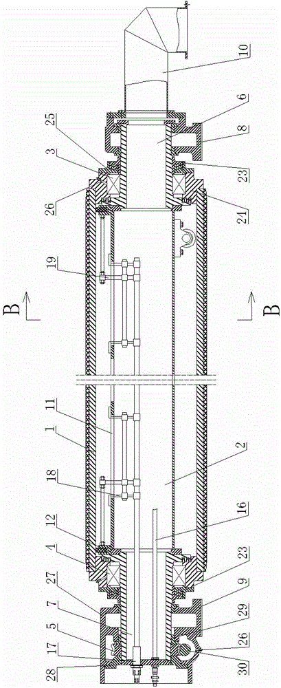
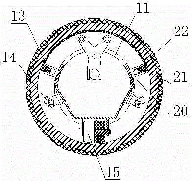
[0015] Such as figure 1 , 2 , 3, the vacuum roller of the paper machine described in the embodiment of the present invention includes a roller body 1, a vacuum box 2, a drive side bearing 3, an operation side bearing 4 and a worm gear adjustment device 5, and the vacuum box 2 is arranged on the roller body 1, the two ends of the vacuum box 2 are respectively connected with the transmission side vacuum box head 6 and the operation side vacuum box head 7, and the transmission side bearing 3 and the operation side bearing 4 are respectively arranged on the transmission side vacuum box head 6 and the operation side vacuum box head 7, on the drive side vacuum box head 6, the outside of the drive side bearing 3 is provided with a support seat 8, on the operation side vacuum box head 7, the outside of the operation side bearing 4 is provided with a suction seat 9, the ...


PUM


Abstract

The invention provides a vacuum carrier roller of a papermaking machine. According to the vacuum carrier roller of the papermaking machine, the structure is simple, the maintenance is convenient, and the dehydration is stable and fruitful. The vacuum carrier roller comprises a roller body, a vacuum box, bearings and a worm and gear adjusting device, wherein the two ends of the vacuum box are separately connected with vacuum box heads, the outer end of the vacuum box head at one side is connected with a vacuum suction port, water suction holes are uniformly distributed in the surface of the roller body, a plurality of water suction openings are uniformly formed in the vacuum box along the axial direction, sealing devices are arranged at the internal wall end, close to the roller body, of the vacuum box, the sealing devices and the vacuum box are in fit so as to form vacuum chambers, the vacuum box comprises a semicircular top and a semi-regular-hexagon bottom, and an adjusting lead screw is further arranged in the vacuum box, is separately connected with water suction opening adjusting rods and end part sealing device adjusting rods and is separately used for adjusting sizes of the water suction openings and adjusting positions of end part sealing devices.

Description

technical field [0001] The invention relates to the technical field of papermaking equipment, in particular to a vacuum idler roller of a papermaking machine. Background technique [0002] After the pulp is uniformly treated in the papermaking process, due to the large amount of water in the pulp, it is necessary to squeeze out the water during the forming process of the paper product. The vacuum roll is a commonly used dehydration part on the paper machine. The speed of the machine plays a decisive role, and it also plays a key role in the physical properties, optical properties, and printability of the paper. The existing vacuum roll has the following problems: the paper sheet is prone to instability or uneven pressure during dehydration, resulting in uneven dehydration of the paper sheet, affecting the dehydration effect, and thus affecting the quality of the paper. Excessive moisture in the paper sheet will lead to pulp rejection or even paper breakage, which will event...

Claims


Application Information

Patent Timeline
Patent Type & Authority Applications(China)
IPC IPC(8): D21F3/10
Inventor 姚洪良
Owner WUXI HONGCHENG PAPER MAKING MACHINERY
Why Eureka
Try Eureka