
Valve bag

A valve pocket and cement technology, applied in the field of valve pockets, can solve problems such as high production costs and achieve the effect of simple strength

Active Publication Date: 2016-03-30
DY PACK VERPACKUNGEN GUSTAV DYCKERHOFF
View PDF5 Cites 2 Cited by
  • Summary
  • Abstract
  • Description
  • Claims
  • Application Information

AI Technical Summary

Problems solved by technology

The thermal material 6 thus forms an essential component of the valve hose 5 and the relatively high unit price of the thermal material 6 leads to high production costs for the valve hose 5 or valve bag 1

Method used


Image

  • Valve bag
  • Valve bag
  • Valve bag

Examples


Embodiment Construction

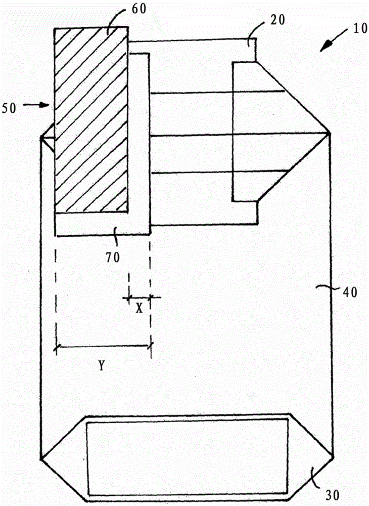
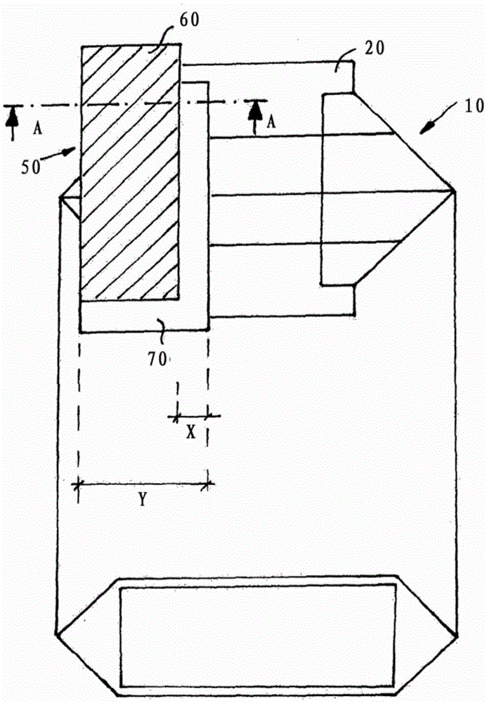
[0020] figure 2 The diagrams of the figure show the valve pocket according to the invention with the thermal material used for the shortening according to the invention. Apart from the modified valve hose, the design of the valve pocket largely corresponds to the solutions known from the prior art.

[0021] The figures show a valve bag 10 according to the invention, which has an upright bottom 20 folded forward at the lower end and a valve bottom 30 at the upper end. Both bases 20 , 30 are connected to each other via a front side 40 and a rear side (not shown) and are folded in the shape of a cross base. In order to illustrate the valve structure, the valve base 20 is shown unfolded, but opened.

[0022] Similar to the prior art, the valve hose 50 protrudes from the upper and lower corners of the valve base 20 on the left side of the valve base. The valve hose 50 here also consists of a thermal material 60 such as a weldable plastic material and a carrier material 70 such ...


PUM


Abstract

The invention concerns a valve bag 10 for bulk material, such as cement, gypsum, granulated material, animal feed, and the like, with a bottom, preferably a cross or block bottom, and with a valve tray which is disposed opposite the bottom and into which valve tubing 50 is inserted in order to fill the valve bag. The valve tubing is formed of a thermal material 60 and a carrier material 70 surrounding the thermal material. The areal proportion of the thermal material is smaller than the areal proportion of the carrier material.

Description

technical field [0001] The invention relates to a valve bag for bulk materials such as cement, gypsum, granular material, animal feed, etc., which has an upright bottom, preferably a cross-shaped bottom (Kreuzboden) or a square bottom, and has a valve bottom opposite the upright bottom , a valve hose for filling the valve pocket is inserted into the valve bottom, wherein the valve hose is formed from a thermal material and a carrier material surrounding the thermal material. Background technique [0002] Such valve bags, mostly made of paper, are generally known and widely used in commerce for fine-grained bulk materials such as cement, gypsum, granular materials, animal feed and the like. Here, commonly used sizes are 5kg, 10kg and 25kg. [0003] The valve base includes a hose-shaped thermovalve, which is coated on the inside with a hotmelt material and which can be melted by the action of heat and closes the valve hose. However, thermal materials do not provide sufficien...

Claims


Application Information

Patent Timeline
IPC IPC(8): B65D30/24B65D30/18
CPCA63J21/00B65D31/08B65D31/14B65D31/142
Inventor 爱德华·利塞克格哈德·舒尔特
Owner DY PACK VERPACKUNGEN GUSTAV DYCKERHOFF
Learn More