
Cable trolley system and cable fixing device

A technology for fixing devices and cables, applied in the direction of electrical components, etc., can solve the problems of poor manufacturability, high manufacturing cost, and the inability to simultaneously compress multiple cables of different sizes and models

Active Publication Date: 2017-11-24
SANY MARINE HEAVY IND
View PDF5 Cites 0 Cited by
  • Summary
  • Abstract
  • Description
  • Claims
  • Application Information

AI Technical Summary

Problems solved by technology

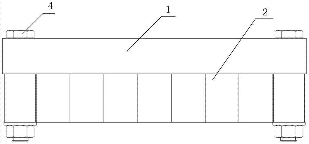
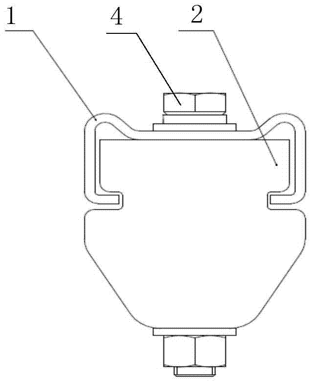
The aforementioned pressing plate 1 needs to be bent inwards to block the pressing block 2. Due to its small bending size, it cannot be directly bent and formed, and needs to be molded and stamped, resulting in poor manufacturability and high manufacturing cost; in addition, it only relies on two ends. The first bolt 4 is compressed, so that the cable with a small diameter in the middle part may not be pressed tightly
Another kind of elongated integral pressing block structure, also can not press multiple different types of cables at the same time, the reliability is even worse
[0003] Patent CN201320266436 discloses a cable fixing device, which includes a base and several pressing blocks installed on the base; a clamping part is arranged on the base, and the clamping part includes a first extension wall and a second extension wall, the first extension wall, the second extension wall The two extension walls are formed by extending vertically from the bottom surface at a certain interval, and the cable clamp is movably arranged between the first and second extension walls, and forms a cable clamping space with the second extension wall. Simultaneously compress a variety of cables of different sizes, but its structure is relatively complicated

Method used


Image

  • Cable trolley system and cable fixing device
  • Cable trolley system and cable fixing device
  • Cable trolley system and cable fixing device

Examples


Embodiment Construction

[0032] It should be noted that, in the case of no conflict, the embodiments of the present invention and the features in the embodiments can be combined with each other. The present invention will be described in detail below with reference to the accompanying drawings and examples.

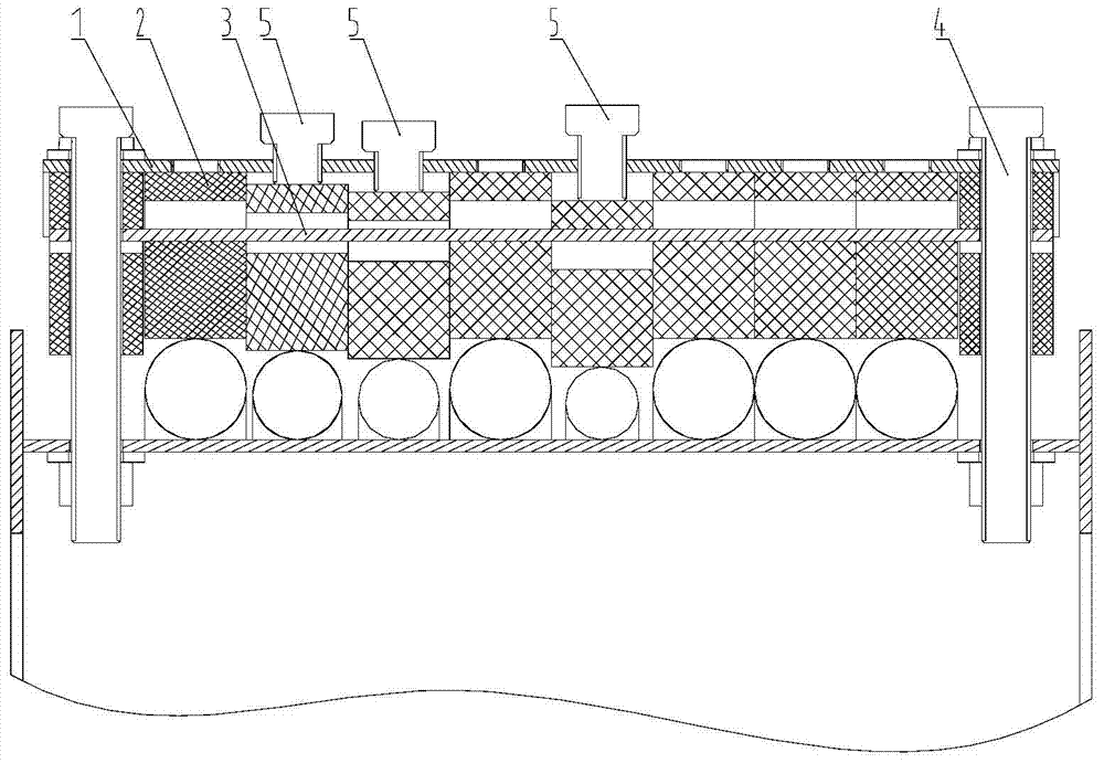
[0033] like image 3 and Figure 4 The cable fixing device shown includes a pressing plate 1, a plurality of pressing blocks 2 are arranged at the bottom of the pressing plate 1, and several pressing blocks 2 are arranged side by side above the cable, a single pressing block 2 is provided with a first through hole in the transverse direction, and the connecting plate 3 passes through several pressing blocks in turn. The first through hole of the pressing block 2 connects several pressing blocks 2, the two ends of the pressing plate 1 and the connecting plate 3 are provided with installation holes, and the pressing blocks 2 located at both ends of the several pressing blocks 2 are vertically prov...


PUM


Abstract

The invention discloses a cable fixing device. The cable fixing device comprises a pressing plate, wherein a plurality of pressing blocks are arranged at the bottom of the pressing plate and arranged above a cable in parallel; each of the pressing blocks is transversely provided with a firs through hole; a connection plate penetrates through the first through holes of the pressing blocks in sequence to connect the pressing blocks together; mounting holes are formed in two ends of the pressing plate and the connection plate; the pressing blocks at two ends of the pressing blocks which are arranged in parallel are vertically provided with second through holes; and a first bolt penetrates through the mounting hole and the second through holes to fixedly connect the pressing plate with the pressing blocks. The cable fixing device has the advantages of being simple in structure, easy to mold and low in cost and being capable of compacting cables with different sizes and types. Finally, the invention furthermore discloses a cable festooning system comprising the cable fixing device.

Description

technical field [0001] The invention relates to the field of cable fixing equipment, in particular to a cable fixing device and a cable trolley system including the fixing device. Background technique [0002] At present, most of the cable briquetting blocks of the towing system adopt the following two structural forms: multi-briquetting structure and elongated integral briquetting structure. like figure 1 As shown, the multi-press block structure is to make both sides of the press block 2 concave, and the press plate 1 is made to bend inward, so that multiple press blocks 2 can be snapped into the press plate 1 without falling, and through the first A bolt 4 can compress various cables with little difference in diameter. The aforementioned pressing plate 1 needs to be bent inwards to block the pressing block 2. Due to its small bending size, it cannot be directly bent and formed, and needs to be molded and stamped, resulting in poor manufacturability and high manufacturin...

Claims


Application Information

Patent Timeline
Patent Type & Authority Patents(China)
IPC IPC(8): H02G3/02
CPCH02G3/02
Inventor 陆茶魁姜成武温正方
Owner SANY MARINE HEAVY IND
Learn More