
Display panel and electronic device

A technology for display panels and electronic equipment, applied in static indicators, instruments, etc., can solve the problems of high area requirements, unfavorable development of narrow borders of display panels, etc., and achieve the effect of reducing area requirements

Active Publication Date: 2016-03-23
XIAMEN TIANMA MICRO ELECTRONICS +1
View PDF6 Cites 11 Cited by
  • Summary
  • Abstract
  • Description
  • Claims
  • Application Information

AI Technical Summary

Problems solved by technology

However, this test method needs to set many test signal sources in the blank area of ​​the display panel, which requires a relatively high area of ​​the blank area of ​​the display panel, which is not conducive to the development of narrow borders of the display panel.

Method used


Image

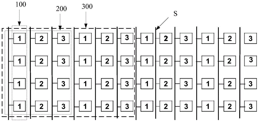
  • Display panel and electronic device
  • Display panel and electronic device
  • Display panel and electronic device

Examples


Embodiment Construction

[0019] As mentioned in the background art, when the display panel in the prior art is tested independently, many test signal sources need to be installed in its blank area, which requires a high area of ​​the blank area, which is not conducive to the development of narrow borders of the display panel.

[0020] In view of this, an embodiment of the present invention provides a display panel, including:

[0021] A plurality of sub-pixel columns, each sub-pixel column is electrically connected to a data line, adjacent N sub-pixel columns are a repeating unit, and are defined as the first sub-pixel column to the Nth sub-pixel column, and the adjacent M repeating units are a sub-pixel group, and are defined as the first repeating unit to the Mth repeating unit, wherein the colors of adjacent sub-pixels in the repeating unit along the sub-pixel column arrangement direction are different, and M and N are both an integer not less than 2;

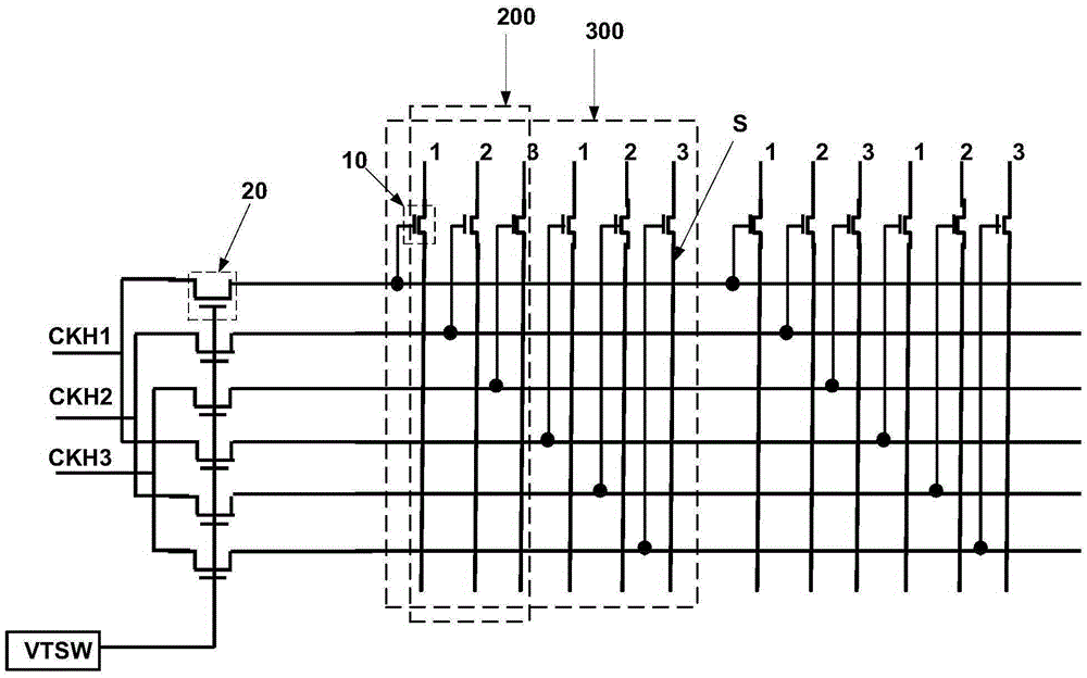
[0022] A plurality of first controllable swi...


PUM


Abstract

The embodiment of the invention relates to a display panel and an electronic device. The display panel includes a plurality of sub pixel columns, a plurality of first controllable switch units, a plurality of second controllable switch units, a plurality of switching-on signal ends and a total control end, wherein N adjacent sub pixel columns are adopted as a repeating unit, M adjacent repeating units are adopted as a pixel group, each first controllable switch unit is corresponding to one sub pixel column, the control ends of first controllable switch units corresponding to the j-th sub pixel columns in the i-th repeating units in the all pixel groups are electrically connected with the second end of one second controllable switch unit through the same lead respectively, the first ends of second controllable switch units corresponding to the j-th pixel columns of all the repeating units in the same pixel group are electrically connected with the same switching-on signal end, and the total control end is electrically connected with the control end of each second controllable switch unit. The display panel can be tested separately, and has lower requirements for the number of test signal sources, and therefore, the development of narrow frames can be benefitted.

Description

technical field [0001] The present invention relates to the field of display technology, and more specifically, to a display panel and electronic equipment including the display panel. Background technique [0002] The display panel is a commonly used display device at present. In order to improve the yield rate of the product, it is usually necessary to test the display substrate to ensure that the display panel can display normally. [0003] In the prior art, the display panel, the driving circuit, the backlight structure and other structures are usually combined to form a complete display device, and then the whole display device is tested to detect whether the display panel displays normally. However, with this test method, when the display panel is abnormal, it is necessary to disassemble each structure in the display device again, separate the display panel, and adjust it. Not only the test process is cumbersome, but the efficiency is low. Low, and it will cause waste...

Claims


Application Information

Patent Timeline
Patent Type & Authority Applications(China)
IPC IPC(8): G09G3/00
CPCG09G3/006
Inventor 王伟鹏杨康鹏黄敏严宇许育民
Owner XIAMEN TIANMA MICRO ELECTRONICS
Learn More