


Quick Research
Generate reliable direction feasibility study reports for your R&D in just a few steps.

Technical Q&A
Discover and master advanced knowledge NOW. Basics, ideas, possibilities, all at once.

Find Solutions
As an expert in R&D theories, this can generate solutions to your technical problems instantly.

Evaluate Feasibility
Analyze your overall solution with one click, know your potential R&D risks in advance.

Monitor Landscape
Get weekly tech updates, stay abreast of the latest tech innovations and key insights.
Diaphragm valve
A diaphragm valve, diaphragm technology, applied in the direction of diaphragm valve, diaphragm, valve details, etc., can solve problems such as can not be replaced
- Summary
- Abstract
- Description
- Claims
- Application Information
AI Technical Summary
Problems solved by technology
Method used
Image

Examples
Embodiment Construction
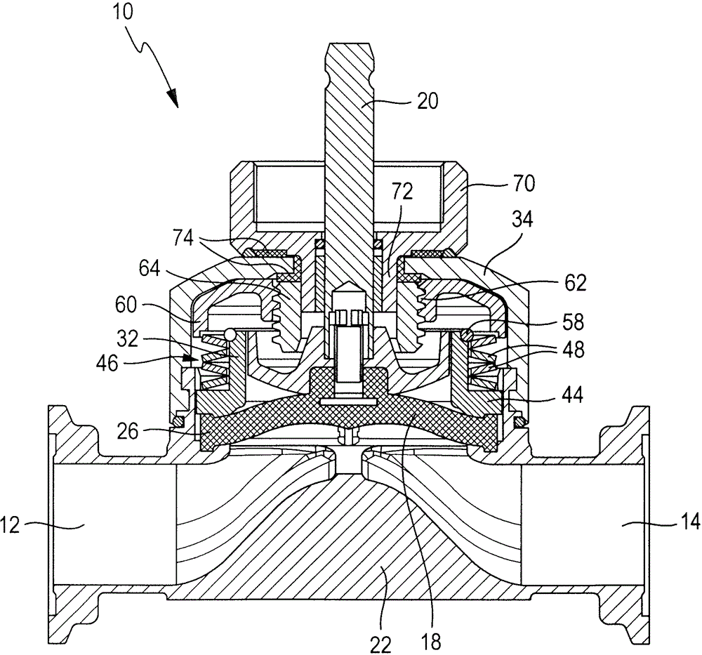
[0024] exist figure 1 The reference symbol 10 denotes a diaphragm valve which has an inlet 12 and an outlet 14 and through which a fluid flows. Inlet 12 and outlet 14 are shown as examples only. Between the inlet 12 and the outlet 14 is located a valve web 16 onto which a membrane 18 can be pushed. The diaphragm 18 is moved in an axial direction by a spindle 20 (which itself is driven by a pneumatic or electric drive not shown) between an open position in which it holds the valve and a closed position. In the open (as shown) or in this closed position, the membrane 18 pushes against the valve web 16 .
[0025] The diaphragm valve 10 has a housing lower part 22 in which the valve web 16 is located and which is open around the valve web 16 so that the fluid at the inlet 12 can flow through the outlet 14 . In the direction past the valve web 16 . The valve web 16 is surrounded by a receiving pot 24 , in which the membrane 18 is mounted, which is seated with its surrounding ed...
PUM
 Abstract
Description
Claims
Application Information
 - R&D Engineer
- R&D Manager
- IP Professional
- Industry Leading Data Capabilities
- Powerful AI technology
- Patent DNA Extraction
Browse by: Latest US Patents, China's latest patents, Technical Efficacy Thesaurus, Application Domain, Technology Topic, Popular Technical Reports.
© 2024 PatSnap. All rights reserved.Legal|Privacy policy|Modern Slavery Act Transparency Statement|Sitemap|About US| Contact US: help@patsnap.com