
Elastic coupling for spline shaft

An elastic coupling and spline shaft technology, applied in elastic couplings, couplings, mechanical equipment and other directions, can solve the problems of accelerated spline wear, impact, large concentricity, etc., to ensure concentricity, reduce wear effect

Active Publication Date: 2016-03-23
CHONGQING ELECTRIC MACHINE FEDERATION
View PDF8 Cites 1 Cited by
  • Summary
  • Abstract
  • Description
  • Claims
  • Application Information

AI Technical Summary

Problems solved by technology

However, the spline shaft will vibrate during high-speed rotation, which will cause impact between the spline and the spline sleeve, which also greatly accelerates the wear of the spline
[0004] Since the elastic coupling is equipped with an elastic buffer structure, such as a spiral groove or parallel groove on the coupling, and elastic gaskets or bellows are used at the connection part of the coupling, the elastic coupling has a buffer , the function of vibration reduction; if the traditional elastic coupling is used in the above-mentioned high-frequency generator set, the above-mentioned problems can be partially solved; but due to the nature of this type of elastic connection, the relative movement between the connected parts is allowed , which brings about the problem that the concentricity between the driving shaft and the transmission shaft is too large when transmitting torque (the concentricity that can be achieved by traditional elastic couplings is 0.5-0.8 mm), the traditional elastic couplings in this respect Performance still needs further technical solutions to solve

Method used


Image

  • Elastic coupling for spline shaft
  • Elastic coupling for spline shaft

Examples


Embodiment Construction

[0015] The present invention will be described in further detail below by means of specific embodiments:

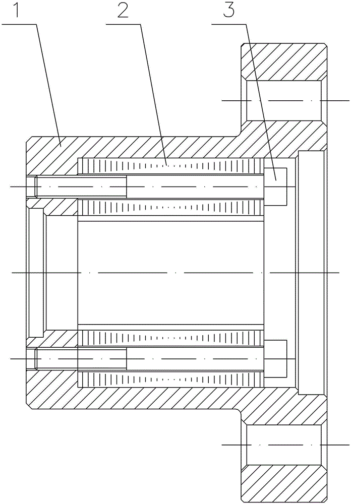
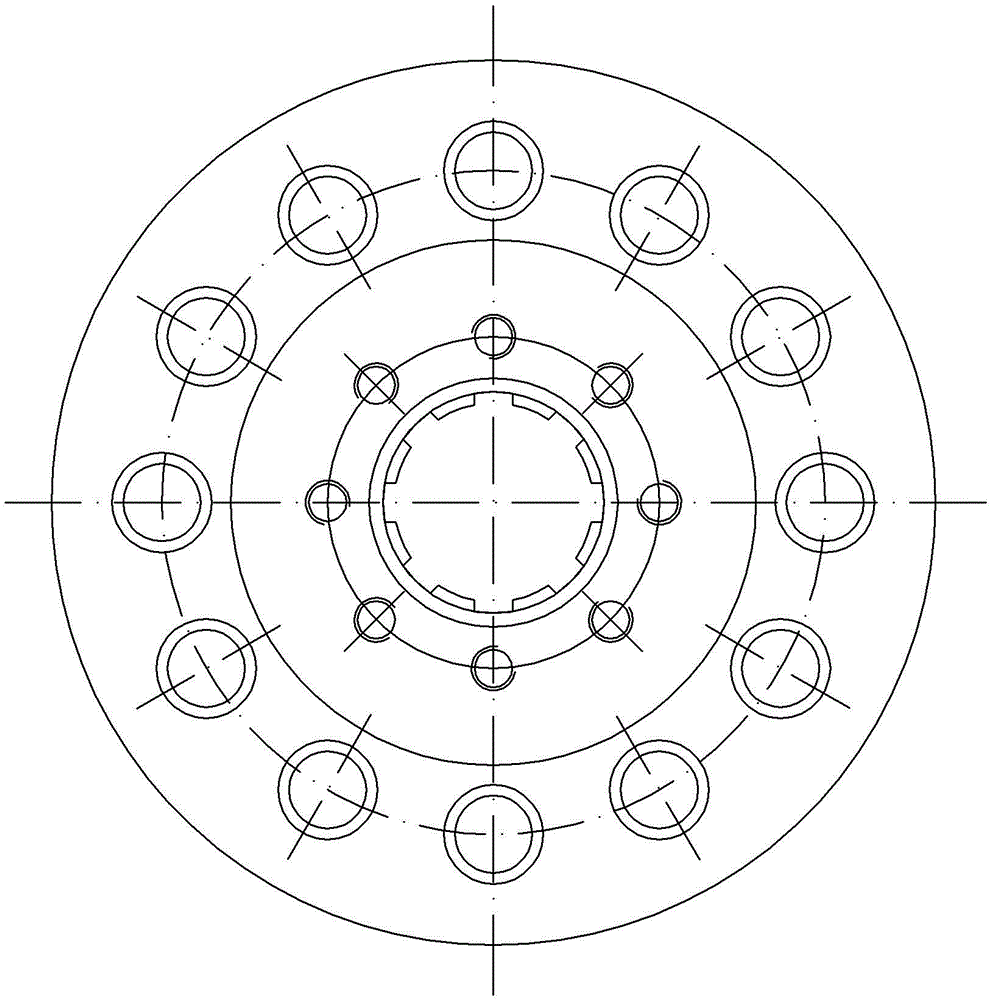
[0016] The reference signs in the accompanying drawings of the specification include: a flange 1 , a spline sleeve 2 , and a screw 3 .

[0017] This example figure 1 , figure 2 Shown: Elastic coupling for spline, including flange 1, spline sleeve 2 and screw 3, spline sleeve 2 is stacked together with several 1 mm thick ring-shaped steel plates, and each ring-shaped steel plate has a There are through holes distributed in the circumferential direction, and the through holes on each annular steel plate form a long through hole for it when stacking. The screws 3 pass through these long through holes and extend into the bottom surface of the counterbore on the flange 1 And through the threaded hole on the bottom surface, it is fixedly connected with the flange plate 1, and at the same time, the entire spline sleeve 2 is pressed on the flange plate 1; the overlapping coeff...


PUM


Abstract

The invention discloses an elastic coupling for a spline shaft. The elastic coupling comprises a flange plate and a spline sleeve; a counter bore is formed in the flange plate; the spline sleeve consists of a plurality of annular metal sheets laminated together; the spline sleeve is tightly pressed in a sinking part of the counter bore by a pressing part, and is coaxial with the counter bore; and spline grooves are peripherally distributed in the inner wall of the spline sleeve. The elastic coupling has the technical effects of reduction of spline wear and capability of guaranteeing lower concentricity.

Description

technical field [0001] The invention relates to the field of couplings, in particular to an elastic coupling for a spline shaft. Background technique [0002] Couplings are mechanical parts used to connect two shafts (driving shaft and driven shaft) in different mechanisms to make them rotate together to transmit torque. There are many types of couplings, which can be divided into rigid couplings and elastic couplings according to the connection mode of the two shafts to be connected. [0003] In the transmission system of high-frequency generator sets, spline shafts and couplings for spline shafts are often used. In traditional technology, rigid couplings are widely used; the splines on the spline shaft fit on the rigid spline sleeves on the coupling to ensure that the concentricity between the driving shaft and the transmission shaft is small enough when torque is transmitted. However, the spline shaft will vibrate during high-speed rotation, which will cause impact betw...

Claims


Application Information

Patent Timeline
Patent Type & Authority Applications(China)
IPC IPC(8): F16D3/56
CPCF16D3/56
Inventor 唐永红
Owner CHONGQING ELECTRIC MACHINE FEDERATION
Learn More