
Movable arm energy-saving system adopting variable-diameter balanced hydraulic cylinder

A technology for balancing hydraulic cylinders and energy-saving systems, applied to mechanically driven excavators/dredgers, etc., can solve problems such as energy waste, heavy weight of hydraulic excavator working devices, and system temperature rise, so as to improve system stability and improve Effects of energy recovery efficiency and efficient reuse

Inactive Publication Date: 2016-03-23
FUJIAN UNIV OF TECH
View PDF7 Cites 0 Cited by
  • Summary
  • Abstract
  • Description
  • Claims
  • Application Information

AI Technical Summary

Problems solved by technology

[0002] During the working process of the hydraulic excavator, the boom swings up and down frequently, and the working device of the hydraulic excavator is heavy and has a large inertia. However, when decelerating and braking, most of the potential energy of the working device is converted into heat energy at the main valve orifice, which not only causes energy waste, but also leads to a rise in system temperature and a reduction in the life of hydraulic components.
[0003] Some hydraulic excavators are equipped with energy storage devices to solve the above problems, but the balance force provided by the energy storage hydraulic cylinders will vary greatly, while the force fed back by the lowering of the excavator arm and the force required for lifting are relatively stable. Both the energy recovery efficiency of the system and the stability of the system need to be further improved: when the boom is lowered, as the accumulator charging pressure gradually increases, the balance force of the accumulator hydraulic cylinder transitions from small to large.

Method used


Image

  • Movable arm energy-saving system adopting variable-diameter balanced hydraulic cylinder
  • Movable arm energy-saving system adopting variable-diameter balanced hydraulic cylinder

Examples


Embodiment 1

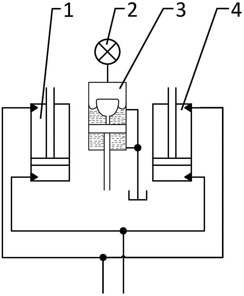
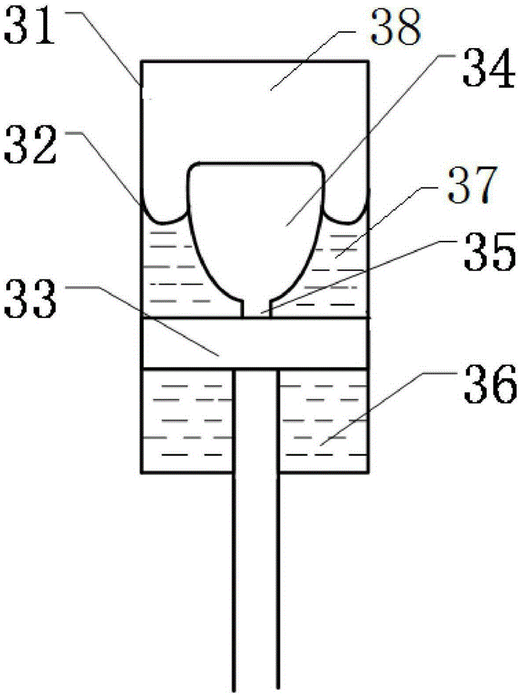
[0014] like figure 1 and figure 2 A boom energy-saving system using a variable diameter balance hydraulic cylinder as shown includes a variable diameter balance hydraulic cylinder 3, a first prime boom hydraulic cylinder 1 and a second prime boom hydraulic cylinder 4; the first prime boom hydraulic cylinder The rodless cavity of 1 is communicated with the rodless cavity of the second prime boom hydraulic cylinder 4; the rod cavity of the first prime boom hydraulic cylinder 1 is communicated with the rod cavity of the second prime boom hydraulic cylinder 4; the diameter is balanced The hydraulic cylinder 3 is connected with the pressure gauge 2; the variable diameter balance hydraulic cylinder 3 includes a casing 31, an elastic diaphragm 32 is arranged in the casing 31, a push rod 34 with an inclined surface is arranged under the elastic diaphragm 32, and the push rod 34 is connected with a piston 33; the piston 33 is connected with a piston rod; above the elastic diaphragm 3...


PUM


Abstract

The invention discloses a movable arm energy-saving system adopting a variable-diameter balanced hydraulic cylinder. The movable arm energy-saving system comprises the variable-diameter balanced hydraulic cylinder, a first original movable arm hydraulic cylinder and a second original movable arm hydraulic cylinder, wherein a rodless cavity of the first original movable arm hydraulic cylinder is communicated with a rodless cavity of the second original movable arm hydraulic cylinder; a rod cavity of the first original movable arm hydraulic cylinder is communicated with a rod cavity of the second original movable arm hydraulic cylinder; the variable-diameter balanced hydraulic cylinder is connected with a pressure gauge; the variable-diameter balanced hydraulic cylinder comprises a shell, an elastic diaphragm is arranged in the shell, a push rod with an inclined surface is arranged below the elastic diaphragm, and the push rod is connected with a piston; the piston is connected with a piston rod; an energy accumulation cavity is arranged above the elastic diaphragm, and a first adjustment cavity is arranged between the elastic diaphragm and the piston; a second adjustment cavity is arranged below the piston; and the first adjustment cavity is communicated with the second adjustment cavity. The movable arm energy-saving system disclosed by the invention is capable of providing a stable additional force for a movable arm, thus realizing efficient reutilization for the recovered energy.

Description

technical field [0001] The invention belongs to the field of machinery, and in particular relates to a boom energy-saving system using a variable diameter balance hydraulic cylinder. Background technique [0002] During the working process of the hydraulic excavator, the boom swings up and down frequently, and the working device of the hydraulic excavator is heavy and has large inertia. However, when decelerating and braking, most of the potential energy of the working device is converted into heat energy at the throttle port of the main valve, which not only causes energy waste, but also leads to an increase in system temperature and a reduction in the life of hydraulic components. [0003] Some hydraulic excavators are equipped with energy storage devices to solve the above problems, but the balance force provided by the energy storage hydraulic cylinders will vary greatly, and the force fed back by the excavator arm’s lowering and the force required for lifting are relati...

Claims


Application Information

Patent Timeline
IPC IPC(8): E02F3/42
CPCE02F3/42
Inventor 张树忠江吉彬唐一文练国富曾寿金叶建华
Owner FUJIAN UNIV OF TECH
Learn More