LED lamp band rolling device

A technology of LED light strips and winding devices, which is applied in the direction of winding strips, transportation and packaging, thin material processing, etc., can solve the problems of reduced production efficiency and low winding efficiency, and achieve the improvement of winding efficiency and connection Quick and easy disassembly

Inactive Publication Date: 2016-03-23
GUANGDONG COOPER OPTOELECTRONICS INC
View PDF6 Cites 15 Cited by
  • Summary
  • Abstract
  • Description
  • Claims
  • Application Information

AI Technical Summary

Problems solved by technology

However, the existing winding devices are usually manually wound, and th...

Method used


Image

  • LED lamp band rolling device
  • LED lamp band rolling device

Examples


Embodiment Construction

[0014] The present invention will be further described in detail below in conjunction with the accompanying drawings and specific embodiments.

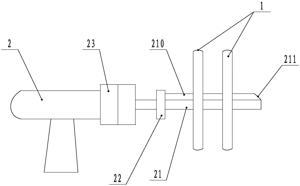
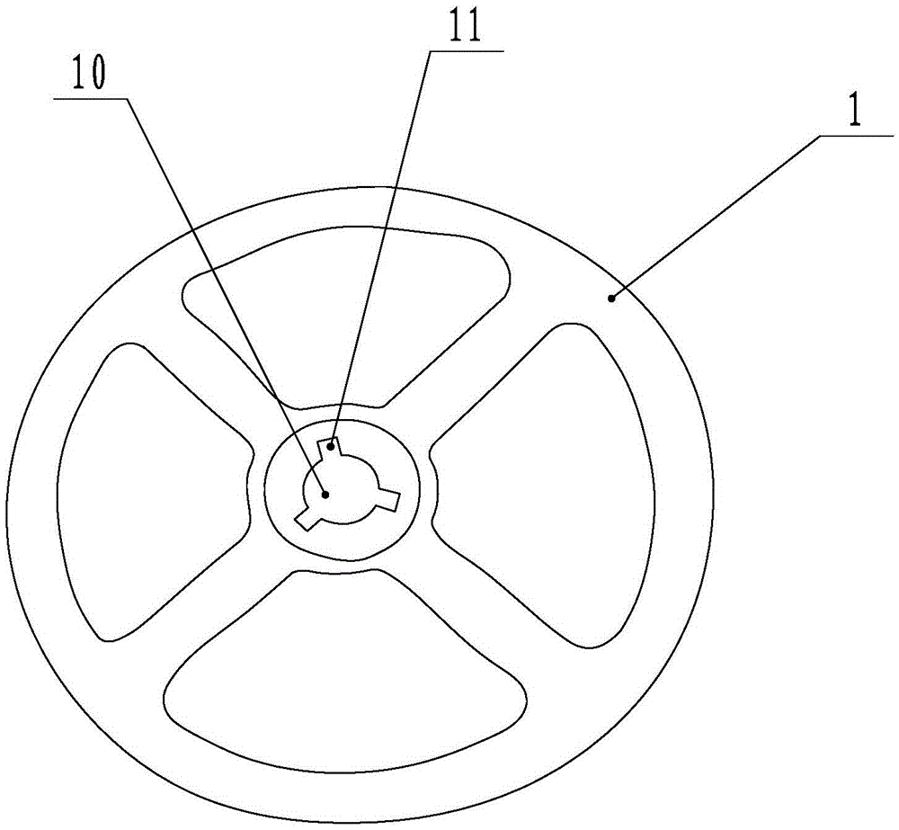
[0015] refer to figure 1 and figure 2 , a LED light strip winding device of the present invention, comprising a winding reel 1 and a driving mechanism 2, the driving mechanism 2 is provided with a rotating shaft 21, the end of the rotating shaft 21 is formed with a rib 210, and the middle of the winding reel 1 is provided with a The socket hole 10 adapted to the rotating shaft 21, the socket hole 10 is formed with a card slot 11 compatible with the rib 210, and the winding reel 1 is clamped on the rib 210 through the card slot 11 so as to be installed and connected to the On the rotating shaft 21, a limit block 22 is arranged in the middle of the rotating shaft 21. The limit block 22 protrudes outward along the circumferential direction of the rotating shaft 21. The limit block 22 is cylindrical and is used to limit the installation...


PUM


Abstract

The invention discloses an LED lamp band rolling device. The LED lamp band rolling device comprises a rolling disc and a drive mechanism. The drive mechanism is provided with a rotating shaft. A protruding ridge is formed at the end of the rotating shaft. A cup joint hole matched with the rotating shaft is formed in the middle of the rolling disc. Clamping grooves matched with the protruding edge are formed in the cup joint hole. The rolling disc is clamped to the protruding ridge through the clamping grooves so as to be installed and connected to the rotating shaft. According to the rolling device, the drive mechanism drives the rolling disc to roll an LED lamp band, and the rolling efficiency of the rolling device is greatly improved compared with manual rolling. Meanwhile, connecting, dismounting and mounting of the rolling disc and the drive mechanism are fast and convenient, and when a user rolls the LED lamp band, the rolling disc only needs to be connected to the rotating shaft in a sleeving manner, meanwhile, the rolling disc is rotated to enable the clamping grooves to be aligned with the protruding ridge of the rotating shaft for clamping and connecting, and accordingly the rolling disc can be installed on the rotating shaft.

Description

technical field [0001] The invention relates to a winding device, in particular to a winding device for LED light strips. Background technique [0002] After the LED light strip is assembled, it usually needs to be wound up by a winding device for storage or transportation. However, the existing winding devices are usually manually wound, and the winding efficiency is relatively low, which reduces the production efficiency. Contents of the invention [0003] In order to overcome the deficiencies of the prior art, the present invention provides an LED light strip winding device, which has the characteristics of high winding efficiency. [0004] The technical solution adopted in the present invention is mainly: an LED light strip winding device, including a winding disk and a driving mechanism, the driving mechanism is provided with a rotating shaft, and a convex rib is formed at the end of the rotating shaft, and the winding The middle part of the reel is provided with a ...

Claims


Application Information

Patent Timeline
IPC IPC(8): B65H18/10B65H75/18
CPCB65H18/10B65H75/185
Inventor 韩丛强
Owner GUANGDONG COOPER OPTOELECTRONICS INC
Why Eureka
Try Eureka