Positioning assisting frame

A positioning aid and frame technology, applied in auxiliary devices, auxiliary welding equipment, welding/cutting auxiliary equipment, etc., can solve laborious and laborious problems, and achieve the effect of low cost, wide use, and simple structure

Inactive Publication Date: 2016-03-23
NO 7 ENG CO LTD OF CHINA RAILWAY 19 BUREAU GRP
View PDF7 Cites 2 Cited by
  • Summary
  • Abstract
  • Description
  • Claims
  • Application Information

AI Technical Summary

Problems solved by technology

[0003] However, the problem existing in the prior art is that since the steel arch is located at a high position, when the steel arch needs to be spliced, the connecting plates need to be correctly positioned and kept for a period of time to install the bolts and nuts. This process requires Supporting the steel arch frame by hand is labor-intensive

Method used


Image

  • Positioning assisting frame
  • Positioning assisting frame
  • Positioning assisting frame

Examples


Embodiment Construction

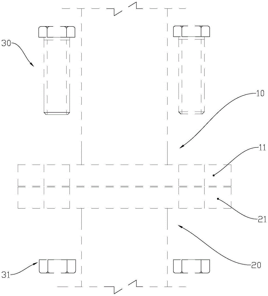
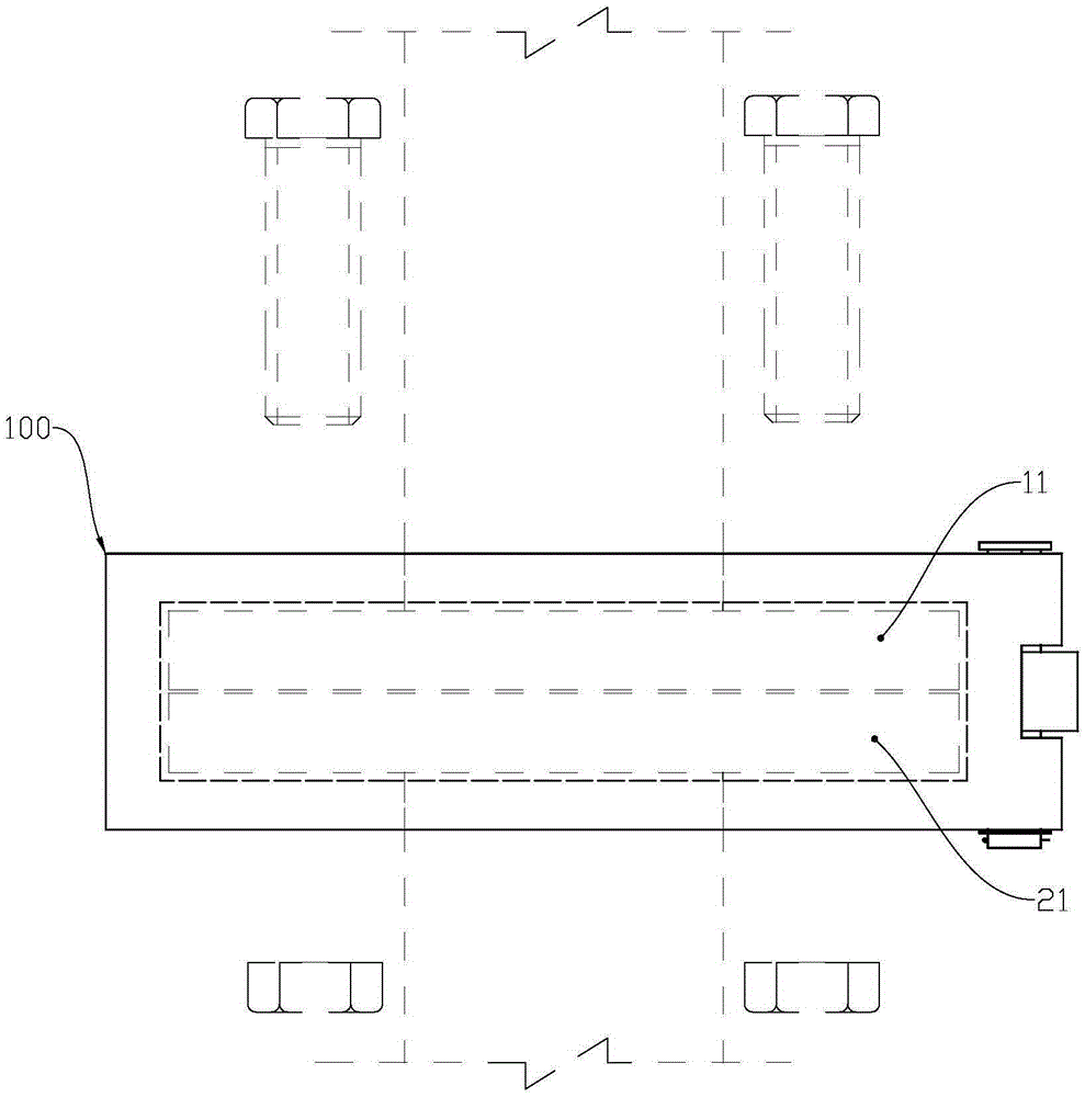
[0034] The invention is an invention and creation aimed at the jointing work of steel arch frames in tunnel construction engineering. Such as figure 1 as shown, figure 1 It is a schematic diagram of steel arch connection; the connection between the first steel arch 10 and the second steel arch 20 is through the first connecting plate 11 on the first steel arch 10 and the second connecting plate on the second steel arch 20 21, after the first connecting plate 11 communicates with the through hole on the second connecting plate 21, each high-strength bolt 30 in the four high-strength bolts 30 passes through the first connecting plate 11 and the second connecting plate 11 simultaneously. After the two connecting plates 21 are joined, a through hole is locked with a high-strength nut 31, so that the first connecting plate 11 and the second connecting plate 21 are tightly connected, thereby realizing the first steel arch 10 and the second steel arch 20 of joining.

[0035] Durin...


PUM


Abstract

The invention provides a positioning assisting frame. The positioning assisting frame comprises a first frame part and a second frame part which are combined to form a square frame, wherein a first clamping groove is formed in the first frame part; a second clamping groove is formed in the second frame part; the first clamping groove and the second clamping groove are combined to form a square frame type clamping groove; the first frame body is hinged with the second frame part; the first frame part is locked to the second frame part by means of threads; the square frame type clamping groove is formed in the inner side of the square frame which is formed by combining the first frame part and the second frame part. According to the positioning assisting frame, connecting plates of two steel arch frames to be connected are slightly aligned and then synchronously clamped into the square frame type clamping groove, and thus the two connecting plates can be positioned; then the second frame part can be swung and locked so as to stably position the positioning assisting frame, and manual continuous positioning is saved, so that both time and force can be saved; the positioning assisting frame is simple in structure, low in cost, and wide in applicable scope.

Description

technical field [0001] The invention relates to the field of building construction, in particular to an auxiliary tool for tunnel construction. Background technique [0002] During the construction of the tunnel, the steel arches need to be connected. The existing connection method is to arrange connecting plates symmetrically at both ends of the arch section and weld them on it, and to open bolt holes symmetrically at the positions corresponding to the four corners of each connecting plate, and to connect two adjacent arch sections. The corresponding bolt holes between the plates are respectively fitted with high-strength bolts and the high-strength nuts are tightened to fix the connection. [0003] However, the problem existing in the prior art is that since the steel arch is located at a high position, when the steel arch needs to be spliced, the connecting plates need to be correctly positioned and kept for a period of time to install the bolts and nuts. This process re...

Claims


Application Information

Patent Timeline
Patent Type & Authority Applications(China)
IPC IPC(8): B23K37/04
CPCB23K37/04
Inventor 刘国强卜德双
Owner NO 7 ENG CO LTD OF CHINA RAILWAY 19 BUREAU GRP
Why Eureka
Try Eureka