
Automatic welding system for crane bogie frames

An automatic welding and trolley frame technology, applied in welding equipment, auxiliary welding equipment, welding/cutting auxiliary equipment, etc., can solve the problems of increased labor intensity, unstable product quality, low production efficiency, etc., and shorten the turning time , good system flexibility, and the effect of improving production efficiency

Inactive Publication Date: 2016-03-23
HENAN SINOKO CRANES
View PDF8 Cites 9 Cited by
  • Summary
  • Abstract
  • Description
  • Claims
  • Application Information

AI Technical Summary

Problems solved by technology

[0002] During the working process of the crane, the traveling mechanism of the cart is under huge working pressure. As an important component of the traveling mechanism of the crane, the trolley frame bears a large dynamic load and static load. In order to ensure the stable operation of the crane, the trolley frame Strict quality control is required in the manufacturing process, and the most important process in the manufacture of the frame is welding. The welding quality is directly related to the manufacturing quality of the whole crane. At present, the welding process of the frame is artificial gas Welding protection, because there are many welding seam positions, it needs to be turned continuously during the welding process, which greatly increases the labor intensity of workers, and manual welding also has the disadvantages of harsh working environment, poor weld seam formation, unstable product quality, and low production efficiency The problem

Method used


Image

  • Automatic welding system for crane bogie frames
  • Automatic welding system for crane bogie frames
  • Automatic welding system for crane bogie frames

Examples


Embodiment 1

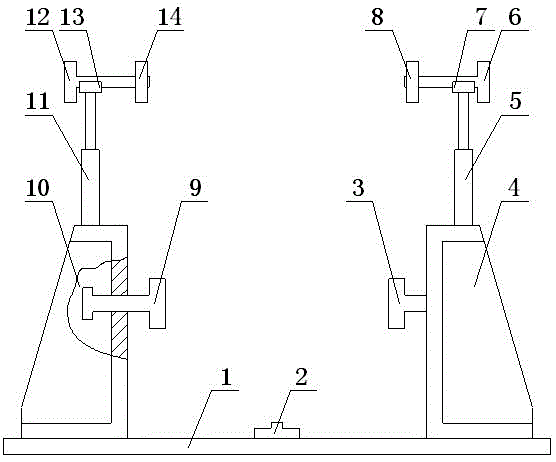
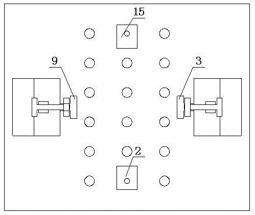
[0019] Such as figure 1 , figure 2 , image 3 , Figure 4 and Figure 5 As shown, an automatic welding system for a crane frame, which includes a flexible tooling fixture and a robot welding system, the flexible tooling fixture includes a base 1, and the upper end of the base 1 is respectively provided with a bottom pressing block A2 and a bottom Pressing block B15, the middle part of the right side of the base 1 is provided with a column A4, the middle part of the column A4 is provided with a compression bolt A3, and the center of the top of the column A4 is provided with a hydraulic rod A5. The top of the hydraulic rod A5 is provided with a connecting block A7, the connecting block A7 is provided with a fixed block A6, the left side of the fixed block A6 is provided with an upper pressure block A8, and the left middle of the base 1 is provided There is a column B10, the middle part of the column B10 is provided with a compression bolt B9, the center of the top of the co...

Embodiment 2

[0022] Such as figure 1 , figure 2 , image 3 , Figure 4 and Figure 5 As shown, an automatic welding system for a crane frame, which includes a flexible tooling fixture and a robot welding system, the flexible tooling fixture includes a base 1, and the upper end of the base 1 is respectively provided with a briquetting block A2 and a briquetting block B14, the middle part of the right side of the base 1 is provided with a column A4, the middle part of the column A4 is provided with a compression bolt A3, and the center of the top of the column A4 is provided with a positioning rod A5, and the positioning rod The top of A5 is provided with a positioning block A6, the top of the positioning block A6 is provided with a pin A12, the middle part of the left side of the base 1 is provided with a column B8, and the middle part of the column B8 is provided with a compression bolt B7 , the center of the top of the column B8 is provided with a positioning rod B9, the top of the p...


PUM


Abstract

The invention relates to an automatic welding system for crane bogie frames. The automatic welding system for crane bogie frames comprises a flexible tool clamp and a robot welding system. The flexible tool clamp comprises a base. A bottom pressing block A and a bottom pressing block B are arranged at the upper end of the base. A stand column A is arranged in the middle of the right side of the base, a pressing bolt A is arranged in the middle of the stand column A, a hydraulic rod A is arranged in the center of the top of the stand column A, and a connection block A is arranged on the top of the hydraulic rod A. A fixing block A is arranged in the connection block A, and an upper pressing block A is arranged on the left side of the fixing block A. A stand column B is arranged in the middle of the left side of the base, a pressing bolt B is arranged in the middle of the stand column B, a hydraulic rod B is arranged in the center of the top of the stand column B, and a connection block B is arranged on the top of the hydraulic rod B. The automatic welding system for crane bogie frames has the beneficial effects of being automatic, stable in welding quality and high in welding efficiency.

Description

technical field [0001] The invention belongs to the field of crane mechanical equipment, and in particular relates to an automatic welding system for a crane platform frame. Background technique [0002] During the working process of the crane, the traveling mechanism of the cart is under huge working pressure. As an important component of the traveling mechanism of the crane, the trolley frame bears a large dynamic load and static load. In order to ensure the stable operation of the crane, the trolley frame Strict quality control is required in the manufacturing process, and the most important process in the manufacture of the frame is welding. The welding quality is directly related to the manufacturing quality of the whole crane. At present, the welding process of the frame is artificial gas Welding protection, because there are many welding seam positions, it needs to be turned continuously during the welding process, which greatly increases the labor intensity of worker...

Claims


Application Information

Patent Timeline
IPC IPC(8): B23K37/00B23K37/02B23K37/04
CPCB23K37/00B23K37/0211B23K37/0443B23K2101/006
Inventor 单丙放崔丽吴瑞龙张三豹
Owner HENAN SINOKO CRANES
Learn More