Axle body and chassis unit

A shaft body and shaft tube technology, applied in the field of shaft body and chassis unit

Active Publication Date: 2016-03-16
SAF HOLLAND GMBH
View PDF5 Cites 0 Cited by
  • Summary
  • Abstract
  • Description
  • Claims
  • Application Information

AI Technical Summary

Problems solved by technology

To date, it has not been possible to use the optimal cross-sectional designs of axle shafts known in the prior art, since such axle shaft designs often conflict with the limited installation space in the chassis area of ​​commercial vehicles

Method used


Image

  • Axle body and chassis unit
  • Axle body and chassis unit
  • Axle body and chassis unit

Examples


Embodiment Construction

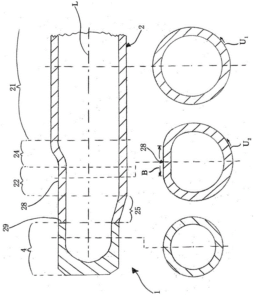
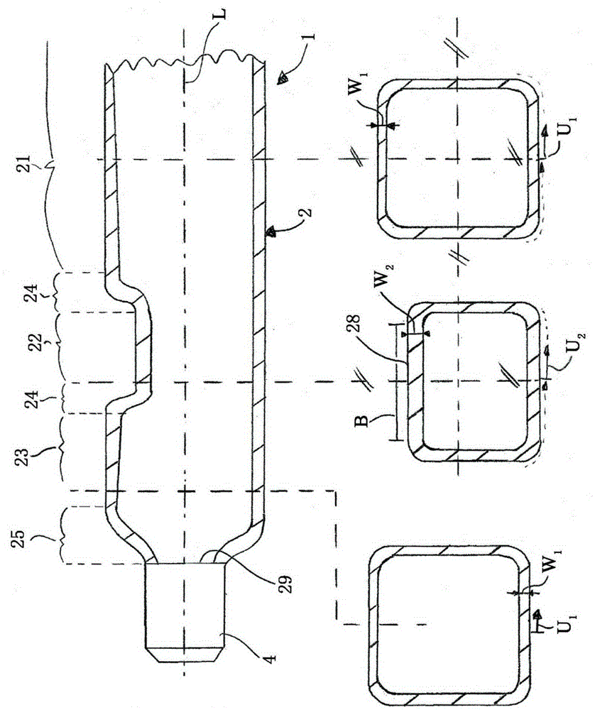
[0028] figure 1It is a sectional view of a preferred embodiment of the shaft body 1 of the present invention. The shaft body 1 has a shaft tube 2 and a shaft head 4, wherein the shaft head 4 is fixed to the shaft tube 2, preferably by friction welding. The shaft tube 2 has a first portion 21 which has a maximum extension along the longitudinal axis L and is in the form of a hollow body. Here, the cross-section or the cross-sectional geometry of the first part 21 of the shaft tube 2 is substantially constant or constant over the course of the longitudinal axis L. As shown in FIG. The first portion 21 adjoins the first transition portion 24, wherein preferably the outer contour of the first portion 21 and its inner contour transition smoothly or tangentially into the multiple curved outer contour and the inner contour of the first transition portion 24, respectively, so that Notching effects which occur at sharp edges of the body under load are reduced in particular. Furtherm...


PUM


Abstract

The present invention relates to an axle body (1) for use in motor vehicles and to a chassis unit having an axle body of said type comprising an axle tube (2) and an axle stub (4), wherein the axle tube (2) is in the form of a hollow body and has a plane-symmetrical first section (21), wherein the axle tube has a second section (22) which is of asymmetrical design with respect to one of the planes of symmetry of the first section (21), and wherein the axle stub (4) is arranged at a distal, rotationally symmetrical end (29) of the axle tube (2).

Description

technical field [0001] The invention relates to an axle body and a chassis unit of a motor vehicle, preferably a commercial vehicle or a utility vehicle. Background technique [0002] Such shafts are generally known in the prior art. It is particularly widespread here to design the shaft body as a hollow body extending substantially smoothly along the longitudinal axis. With regard to the bending and torsional strength of the shaft, the design as a hollow body is particularly advantageous when compared with a solid shaft, since a hollow shaft can achieve a much greater bending resistance while maintaining the same weight strength and torsional strength. The bending and torsional strength of the shaft is particularly dependent on the design of the cross section. To date, it has not been possible to use the optimal cross-sectional designs of the axle shafts known in the prior art, since such axle shaft designs often conflict with the limited installation space in the chassi...

Claims


Application Information

Patent Timeline
Patent Type & Authority Applications(China)
IPC IPC(8): B60B35/04B60B35/08B60B35/02B60B35/06B60B35/16B60G21/05
CPCB60B35/025B60B35/04B60B35/06B60B35/163B60G2206/32B60G2300/026B60B35/08B60B2900/111B60B2900/351
Inventor 奥拉夫·德鲁斯
Owner SAF HOLLAND GMBH
Why Eureka
Try Eureka