
Fixing column device used for PCB and driven by chain

A PCB circuit board and chain transmission technology, applied in the direction of electrical components, electrical components, etc., can solve problems such as damage to fixing nails, affecting the efficiency of circuit board loading and unloading, and affecting equipment use and maintenance

Inactive Publication Date: 2016-03-16
方志彦
View PDF2 Cites 0 Cited by
  • Summary
  • Abstract
  • Description
  • Claims
  • Application Information

AI Technical Summary

Problems solved by technology

However, this method often needs to manually depress the elastic hook when dismounting, which is inconvenient to operate and in some cases, the elastic hook is difficult to depress, which affects the loading and unloading efficiency of the circuit board, and even damages the fixing nail. Overall equipment use and maintenance

Method used


Image

  • Fixing column device used for PCB and driven by chain
  • Fixing column device used for PCB and driven by chain

Examples


Embodiment Construction

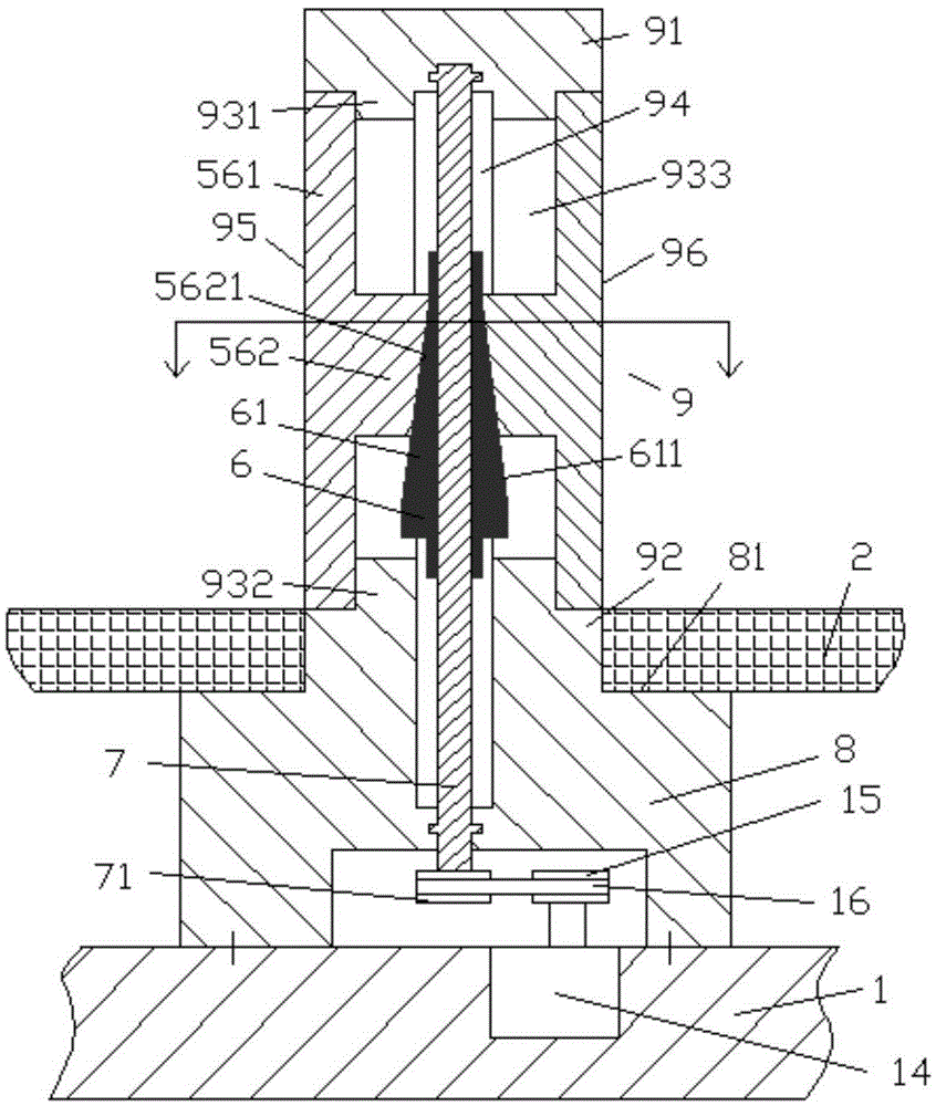
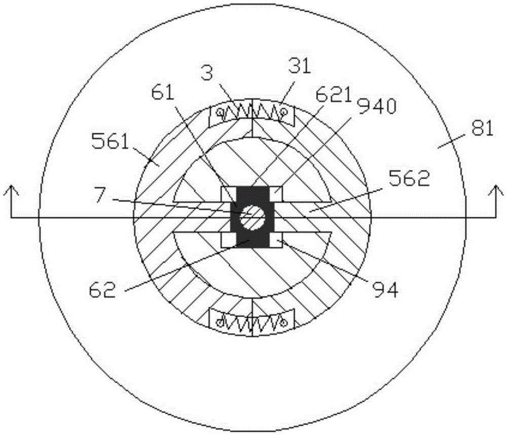
[0011] Combine below Figure 1-2 , the present invention will be described in detail.

[0012] According to an embodiment, a chain-driven fixing post device for a PCB circuit board is used to be fixedly connected to the frame body 1 so as to fix the PCB circuit board 2 on the frame body 1, and the fixing post device includes a bottom The fixed body 8 fixedly connected with the frame body 1, the fixed body 8 includes a bottom shoulder portion having a shoulder surface 81 for carrying the back of the PCB circuit board and an integrally formed shoulder surface 81 perpendicular to the Vertical post part 9, said vertical post part 9 comprises the cylindrical root part 92 integrally connected with said shoulder surface 81 of the bottom and used for engaging with the fixing hole on the PCB circuit board, the cylindrical top part 91 at the top end and the intermediary A generally cylindrical intermediate connecting portion between the cylindrical root 92 and the cylindrical top 91, w...


PUM


Abstract

The invention discloses a fixing column device used for a PCB and driven by a chain. The fixing column device is used for fixedly connecting a frame body (1) so as to fix the PCB (2) on the frame body (1). The fixing column device comprises a fixed body (8) of which the base is fixedly connected with the frame body (1); the fixed body (8) comprises a base shoulder part having a shoulder side (81) for bearing the back of the PCB, and an integrated perpendicular column part (9) perpendicular to the shoulder side (81); and the perpendicular column part (9) comprises a cylindrical root part (92) which is located at bottom, integrally connected with the shoulder side (81) and used for jointing a fixing hole on the PCB, a cylindrical top part (91) located at top end, and a generally cylindrical middle connection part located between the cylindrical root part (92) and the cylindrical top part (91).

Description

technical field [0001] The invention belongs to the field of PCB circuit boards, and more specifically relates to a chain-driven fixing post device for PCB circuit boards. Background technique [0002] Generally speaking, the installation of the PCB circuit board in the bracket of the equipment needs to be stable and reliable. The commonly used method or method is to punch holes on the control box, first install the pad nails for fixing the circuit board, and then pad the insulating gasket to fix the circuit board on it with screws, which can also be fixed with glue. [0003] However, this installation method requires manual screw tightening, and in some occasions where space is limited or operation time is limited, this fixing method is limited. [0004] Some existing fixed installation methods also include the use of plastic fixing nails with elastic hooks. In this way, the step of manually tightening the screws can be eliminated, and the circuit board can also be fixed....

Claims


Application Information

Patent Timeline
IPC IPC(8): H05K13/00
CPCH05K13/0061H05K13/0015
Inventor 方志彦
Owner 方志彦
Learn More