Power coupling device

A technology of couplers and wires, applied in the field of wireless power transmission, can solve the problems of limiting the ability of devices to capture wireless power and restricting the efficient transmission of power

Inactive Publication Date: 2016-03-16
EMPIRE TECH DEV LLC
View PDF2 Cites 0 Cited by
  • Summary
  • Abstract
  • Description
  • Claims
  • Application Information

AI Technical Summary

Problems solved by technology

However, the size of these devices limits the ability to efficiently transfer power wirelessly
As a result, the device's ability to capture wireless power is limited

Method used


Image

  • Power coupling device
  • Power coupling device
  • Power coupling device

Examples


Embodiment Construction

[0026] In the following detailed description, reference is made to the drawings forming a part thereof. In the drawings, unless the context dictates otherwise, similar symbols generally identify similar components. The illustrative embodiments described in the detailed description, drawings, and claims are not meant to be limiting. Without departing from the spirit or scope of the subject matter presented herein, other embodiments may be utilized, and other changes may be made. As generally described herein and illustrated in the drawings, aspects of the present disclosure can be arranged, substituted, combined, separated and designed in a variety of different configurations, all of which are explicitly contemplated herein To.

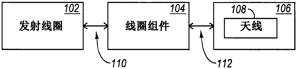
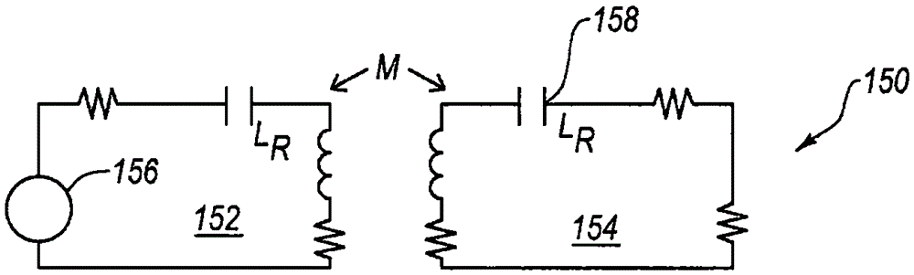
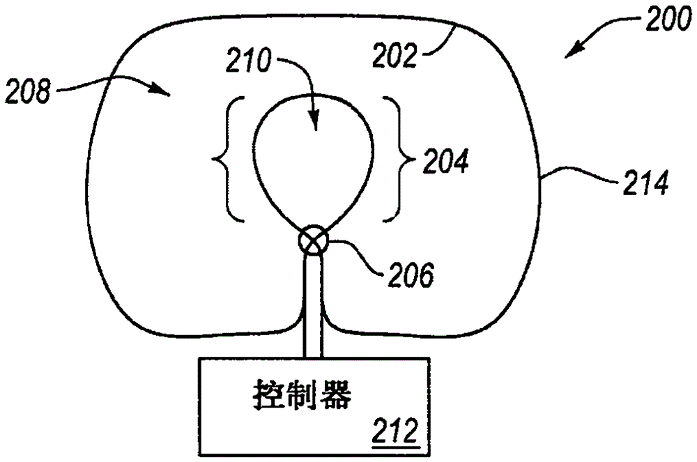
[0027] The exemplary embodiment relates to a power coupler system capable of enhancing power wirelessly transmitted to various devices. An example coupler system may include a coil assembly. The coil assembly can receive a signal that can be used to t...


PUM


Abstract

Systems and methods to wirelessly transmit power are provided. A coil assembly is provided. In some examples, the coil assembly is configured to generate a signal in response to an ambient field, and to magnetically couple with a device to deliver power to the device.

Description

Technical field [0001] The present disclosure relates generally but not exclusively to wireless power transmission. Background technique [0002] Unless otherwise indicated herein, the material described in this section is not prior art to the claims in this application, and is not admitted to be prior art by inclusion in this section. [0003] Wireless power transmission is a technology capable of wirelessly transmitting power to a device. For example, this technology can be used to charge the device's battery using a signal that is wirelessly transmitted to the device. The wireless power transmission system can be deployed in various places such as coffee shops and airports. [0004] However, the nature of the device that needs to be charged can complicate the process. Many devices that can benefit from wireless power transfer, such as smart phones, tablet devices, and game controllers, are small and portable. However, the size of these devices limits the ability to efficiently...

Claims


Application Information

Patent Timeline
Patent Type & Authority Applications(China)
IPC IPC(8): H02J50/12H02J5/00
CPCH02J50/12H02J50/001
Inventor K·S·费恩E·克鲁格里克
Owner EMPIRE TECH DEV LLC
Why Eureka
Try Eureka