A pluggable optical module

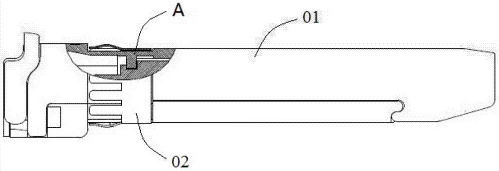
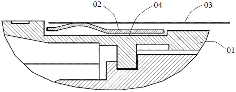
A technology of optical modules and conductive parts, applied in the field of optical modules, can solve the problems of electronic equipment interference, leakage, and the outer surface of the electromagnetic interference shielding clip 02 cannot be completely fitted, etc., and achieve the effect of reducing electromagnetic wave radiation and avoiding interference.

Active Publication Date: 2017-11-07
HISENSE BROADBAND MULTIMEDIA TECH
View PDF6 Cites 0 Cited by
  • Summary
  • Abstract
  • Description
  • Claims
  • Application Information

AI Technical Summary

Problems solved by technology

In the pluggable optical module in the prior art, the electromagnetic interference shielding clip 02 is in surface contact with the housing 01. Due to the limitation of process accuracy, the inner surface of the electromagnetic interference shielding clip 02 and the outer surface of the housing 01 cannot be completely attached. close together, resulting in a gap 04 between the electromagnetic interference shielding clip 02 and the housing 01, the electromagnetic wave in the optical module cage 03 will leak out of the optical module cage 03 through the gap 04, causing interference to other nearby electronic equipment

Method used


Image

  • A pluggable optical module
  • A pluggable optical module
  • A pluggable optical module

Examples


Embodiment Construction

[0017] The following will clearly and completely describe the technical solutions in the embodiments of the present invention with reference to the accompanying drawings in the embodiments of the present invention. Obviously, the described embodiments are only some, not all, embodiments of the present invention. Based on the embodiments of the present invention, all other embodiments obtained by persons of ordinary skill in the art without making creative efforts belong to the protection scope of the present invention.

[0018] In describing the present invention, it is to be understood that the terms "center", "upper", "lower", "front", "rear", "left", "right", "vertical", "horizontal", The orientations or positional relationships indicated by "top", "bottom", "inner", "outer", etc. are based on the orientations or positional relationships shown in the drawings, and are only for the convenience of describing the present invention and simplifying the description, rather than in...


PUM


Abstract

Some embodiments of the present disclosure disclose a pluggable optical module, comprising a housing and an electromagnetic interference shielding clip clamped on the housing; a conductive member is provided between the housing and the electromagnetic interference shielding clip; and when the pluggable optical module is inserted into an optical module cage, the conductive member can block a gap between the housing and the electromagnetic interference shielding clip.

Description

technical field [0001] The invention relates to the technical field of optical modules, in particular to a pluggable optical module. Background technique [0002] In optical fiber communication technology, optical signals are used as information carriers for high-speed, long-term, and reliable information transmission. The function of the optical module is photoelectric conversion, that is, the sending end converts the electrical signal into an optical signal, and after transmission through the optical fiber, the receiving end converts the optical signal into an electrical signal. [0003] figure 1 is a partial cross-sectional view of a pluggable optical module in the prior art, figure 2 for figure 1 The enlarged view of part A of , including the housing 01 and the electromagnetic interference shielding clip 02 clamped on the housing 01, when the pluggable optical module is inserted into the optical module cage 03, the electromagnetic interference shielding clip 02 is lo...

Claims


Application Information

Patent Timeline
Patent Type & Authority Patents(China)
IPC IPC(8): G02B6/42H05K9/00
Inventor 赵伟潘红超刘寅龙崔伟于琳
Owner HISENSE BROADBAND MULTIMEDIA TECH
Why Eureka
Try Eureka