Sealing device between flue gas recirculation cover and trolley of sintering machine

A technology of flue gas circulation and sealing device, which is applied to furnace types, furnaces, lighting and heating equipment, etc., can solve the problems of destroying the continuity of sintering production, short service life of rubber sheets, affecting the production efficiency of sintering machines, etc., to ensure long-term protection. The effect of continuous and stable operation and long service life

Active Publication Date: 2016-03-16
JIGANG INT ENG & TECH CO LTD
View PDF5 Cites 1 Cited by
  • Summary
  • Abstract
  • Description
  • Claims
  • Application Information

AI Technical Summary

Problems solved by technology

[0002] During the production process of the sintering machine, the high-temperature oxygen-containing flue gas in the large flue circulates to the flue gas circulation hood of the sintering machine to participate in the sintering process, so the sealing between the flue gas circulation hood and the trolley is particularly important. The seal between cars usually adopts rubber plate type seal. Due to the high temperature, friction and collision during operation of the trolley, the service life of the rubber plate is very short. Usually, the rubber plate will be aged and damaged after running for 3 months. The damaged background car and smoke The air leakage rate between the hoods is as high as 30%-40%, which affects the energy saving and emission reduction effect of the sintering process. After the rubber plate is damaged, it needs to stop production before replacing it, which will destroy the continuity of sintering production and affect the production efficiency of the sintering machine

Method used


Image

  • Sealing device between flue gas recirculation cover and trolley of sintering machine
  • Sealing device between flue gas recirculation cover and trolley of sintering machine

Examples


Embodiment Construction

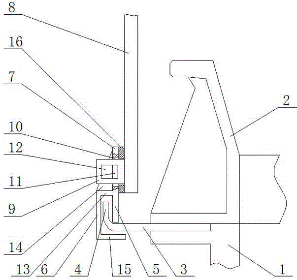
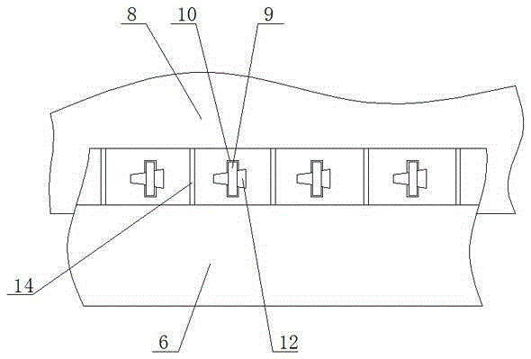
[0008] A sealing device between a sintering machine flue gas circulation hood and a trolley according to the present invention includes a trolley 1, a fence 2 is arranged on both sides of the trolley 1, a lower sealing support plate 3 is installed on the outer side of the fence 2, and a lower sealing support Flange 4 is arranged on the outside of board 3, and flange 4 is perpendicular to the horizontal plane, and the length direction of flange 4 is parallel to the length direction of fence 2, and the side of flange 4 close to fence 2 is provided with inner baffle 5, and flange 4 is away from One side of the fence 2 is provided with an outer baffle 6, and the tops of the inner baffle 5 and the outer baffle 6 are connected with the connecting plate 7, and the connecting plate 7 is connected with the circulating smoke hood 8 of the sintering machine through a connecting piece. The present invention forms a labyrinth seal structure through the inner baffle plate 5, the outer baffle...


PUM


Abstract

The invention discloses a sealing device between a flue gas recirculation cover and a trolley of a sintering machine. The sealing device comprises the trolley, and breast boards are arranged on the two sides of the trolley. The sealing device is characterized in that lower sealing supporting boards are arranged on the outer sides of the breast boards; folding edges are arranged on the outer sides of the lower sealing supporting boards and are perpendicular to the horizontal plane; the length direction of the folding edges is parallel to that of the breast boards; inner baffles are arranged on the sides, close to the breast boards, of the folding edges, and outer baffles are arranged on the sides, far away from the breast boards, of the folding edges; the tops of the inner baffles and the tops of the outer baffles are connected with a connecting plate; and the connecting plate is connected with the flue gas recirculation cover of the sintering machine through a connecting piece. The service life is long, the sealing structure can be replaced without shutdown, the air leakage rate of the part between the trolley and the flue gas recirculation cover can be lowered to be below 10%, and the energy saving and emission reducing effect of the sintering process is guaranteed; and along with sintering production, the sealing effect is gradually enhanced on the original basis, and long-term continuous and stable running of the sintering process can be guaranteed.

Description

technical field [0001] The invention relates to a flue gas circulation device of a sintering machine, in particular to a sealing device between a flue gas circulation cover of a sintering machine and a trolley. Background technique [0002] During the production process of the sintering machine, the high-temperature oxygen-containing flue gas in the large flue circulates to the flue gas circulation hood of the sintering machine to participate in the sintering process, so the sealing between the flue gas circulation hood and the trolley is particularly important. The seal between cars usually adopts rubber plate type seal. Due to the high temperature, friction and collision during operation of the trolley, the service life of the rubber plate is very short. Usually, the rubber plate will be aged and damaged after running for 3 months. The damaged background car and smoke The air leakage rate between the hoods is as high as 30%-40%, which affects the energy saving and emission...

Claims


Application Information

Patent Timeline
IPC IPC(8): F27B21/08
CPCF27B21/00
Inventor 战立刚翁旭霞李兵孙雅文刘冬梅
Owner JIGANG INT ENG & TECH CO LTD
Why Eureka
Try Eureka