
Clamp with rulers

A ruler and fixture technology, applied in the mechanical field, can solve problems such as poor versatility, troublesome operation, complex structure, etc., and achieve the effects of stable clamping, convenient and fast operation, and improved processing efficiency

Inactive Publication Date: 2016-03-16
刘文生
View PDF5 Cites 1 Cited by
  • Summary
  • Abstract
  • Description
  • Claims
  • Application Information

AI Technical Summary

Problems solved by technology

The existing clamping and fixing tools are complex in structure, cumbersome to operate, and can only fix a single workpiece, which has poor versatility. Therefore, further research is needed

Method used


Image

  • Clamp with rulers
  • Clamp with rulers
  • Clamp with rulers

Examples


Embodiment Construction

[0018] The present invention will be further described below in conjunction with the drawings.

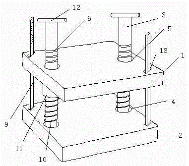
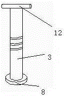
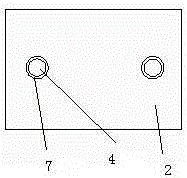
[0019] Such as Figure 1 to Figure 4 As shown, a clamp with a ruler includes a symmetrically arranged upper splint 1, a lower splint 2, and an adjusting rod 3 connected to the upper splint 1, the lower splint 2, and the upper splint 1 and the lower splint 2 realize the clamping function of the workpiece, The adjusting rod 3 adjusts the distance between the two to realize the clamping of workpieces of different heights. The lower clamping plate 2 is provided with a lower insertion hole 4, and the upper clamping plate 1 is provided with a corresponding lower insertion hole 4 The upper socket 5, the upper socket 5 is provided with an internal thread, the adjustment rod 3 passes through the upper socket 5, the lower socket 4 in turn, and is provided with an external thread 6 that matches the internal thread, and rotates the adjustment rod 3. The position of the upper splint through the i...


PUM


Abstract

The invention discloses a clamp with rulers. The clamp with the rulers comprises an upper clamping plate, a lower clamping plate and adjusting rods. The upper clamping plate and the lower clamping plate are symmetrically arranged, and the adjusting rods are connected with the upper clamping plate and the lower clamping plate. Lower inserting holes are formed in the lower clamping plate, and upper inserting holes corresponding to the lower inserting holes are formed in the upper clamping plate. Inner threads are arranged in the upper inserting holes. The adjusting rods sequentially penetrate the upper inserting holes and the lower inserting holes and are provided with outer threads matched with the inner threads. Grooves formed along the circumferential sides of the lower inserting holes are formed in the bottom of the lower clamping plate. Base plates are arranged on the lower portions of the adjusting rods. The base plates are embedded in the grooves. The rulers are arranged on one sides of the adjusting rods. Inserting grooves are formed in the positions, located on the side portions of the adjusting rods, on the upper clamping plate. The rulers are inserted in the inserting grooves. The lower ends of the rulers are provided with bases, and magnets are arranged on the lower portions of the bases. Iron sheets are arranged at the positions, corresponding to the inserting grooves, of the lower clamping plate. The rulers are made of elastic pieces. The clamp with the rulers can be adjusted in advance according to the practical heights of workpieces, the detachable rulers are used flexibly, and the structure is simple.

Description

Technical field [0001] The invention belongs to the technical field of machinery, and specifically relates to a clamp with a ruler. Background technique [0002] In order to ensure the accuracy of the product processing, people generally fix the product with a clamping jig and then realize the processing operation. Therefore, the clamping jig is very important for the clamping force and stability of the product. The existing clamping and fixing tools are complicated in structure, cumbersome to operate, and can only fix a single workpiece, and have poor versatility. Therefore, further research is needed. Summary of the invention [0003] In order to solve the deficiencies in the prior art, the present invention provides a fixture with a ruler, which can be pre-adjusted according to the height of the actual workpiece, which saves the time consumption of actual processing, improves the processing efficiency, and the detachable ruler is flexible to use , The structure is simple, has ...

Claims


Application Information

Patent Timeline
Patent Type & Authority Applications(China)
IPC IPC(8): B25B11/00
CPCB25B11/00
Inventor 刘文生
Owner 刘文生
Learn More