Circuit and method for controlling power of laser tube on basis of PWM signal

A PWM signal and power circuit technology, applied in control/regulating systems, regulating electrical variables, instruments, etc., can solve the problems of no redundancy in the system, large compensation errors, and low precision, and achieve accurate power control, system stability, and precision. high effect

Active Publication Date: 2016-03-09
SHANGHAI JINDUN FIRE FIGHTING INTELLIGENT TECH CO LTD
View PDF7 Cites 0 Cited by
  • Summary
  • Abstract
  • Description
  • Claims
  • Application Information

AI Technical Summary

Problems solved by technology

The traditional laser tube output power control loop uses a negative feedback amplifier circuit to compensate the power of the laser tube. The system has no redundancy (usually refers to increasing the reliability of the system through multiple backups), and has disadvantages such as low accuracy and poor reliability.
[0003] Moreover, in the prior art, the temperature compensation of the laser tube mostly uses a temperature sensor and a temperature compensation analog circuit to compensate the temperature of the laser tube, that is, the analog value of the temperature compensation signal is directly input into the laser tube, and the compensation error is relatively large.

Method used


Image

  • Circuit and method for controlling power of laser tube on basis of PWM signal

Examples


Embodiment Construction

[0023] In order to understand the technical content of the present invention more clearly, the following examples are given in detail.

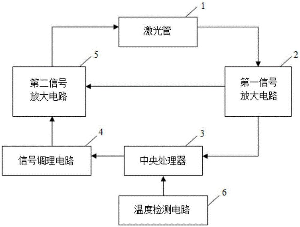
[0024] see figure 1 , a laser tube power circuit based on PWM signal control, including a laser tube 1, a first signal amplifying circuit 2, a central processing unit 3 (Central Processing Unit, CPU for short), a signal conditioning circuit 4, a second signal amplifying circuit 5 and a temperature detection circuit 6. Wherein, the laser tube 1 is a low-power laser tube, and a laser tube with a power less than 10 mW is selected in this embodiment.

[0025] The central processing unit 3 controls the output signal of the I / O port through software, and sends the signal to the second signal amplifying circuit 5, and outputs a control signal after being amplified by the second signal amplifying circuit 5 to control the operation of the laser tube 1.

[0026] In this embodiment, between the central processing unit 3 and the second signal amplifyin...


PUM


Abstract

The invention provides a circuit and method for controlling the power of a laser tube on the basis of a PWM signal. The circuit comprises a first signal amplification circuit, a central processor and a second signal amplification circuit; the first signal amplification circuit is used for receiving and amplifying a laser feedback signal output by the laser tube after the laser tube is started; the central processor is used for receiving the laser feedback signal output by the first signal amplification circuit and regulating and outputting the PWM signal according to the laser feedback signal; the second signal amplification signal is used for receiving and processing the laser feedback signal output by the first signal amplification circuit and the PWM signal output by the central processor, outputting a control signal and transmitting the control signal to the laser tube. According to the circuit and method, two closed feedback circuits are adopted to compensate the output power of the laser tube, so that the system reliability is far higher than that of an existing single-circuit control circuit.

Description

technical field [0001] The invention relates to the field of optoelectronic technology, in particular to a laser tube power circuit and method thereof, in particular to a laser tube power circuit and method based on a PWM (PulseWidthModulation) signal. Background technique [0002] At present, laser tubes are widely used in many fields such as industry, communication, medical treatment, and military affairs. With the development of science and technology, the requirements for laser tube power are getting higher and higher, followed by the requirement of precise and stable control of the output power of laser tubes. The laser output power control circuit is an important part of the laser system, and its accuracy directly affects the stability of the laser tube, so it is necessary to improve the performance of the corresponding laser tube output power control circuit. The traditional laser tube output power control loop uses a negative feedback amplifier circuit to compensate...

Claims


Application Information

Patent Timeline
Patent Type & Authority Applications(China)
IPC IPC(8): G05F1/66
CPCG05F1/66
Inventor 石磊徐鸿玉
Owner SHANGHAI JINDUN FIRE FIGHTING INTELLIGENT TECH CO LTD
Why Eureka
Try Eureka