Method for forming concave-convex structure on substrate and method for making mold

A concave-convex structure and substrate technology, which can be applied to home appliances, other home appliances, instruments, etc., can solve problems such as luminance fading and easily affecting display quality

Active Publication Date: 2018-12-14
UBRIGHT OPTRONICS CORP
View PDF13 Cites 0 Cited by
  • Summary
  • Abstract
  • Description
  • Claims
  • Application Information

AI Technical Summary

Problems solved by technology

In addition, people use portable electronic devices at close range, and the phenomenon of rainbow patterns is likely to affect the display quality
Traditionally, the backside of the substrate is designed with high haze to reduce the above-mentioned optical defects, but the luminance also declines accordingly

Method used


Image

  • Method for forming concave-convex structure on substrate and method for making mold
  • Method for forming concave-convex structure on substrate and method for making mold
  • Method for forming concave-convex structure on substrate and method for making mold

Examples


Embodiment Construction

[0069] This description is of the best mode currently contemplated for carrying out the invention. The invention is described herein with reference to various embodiments and drawings. This description has been produced to illustrate the general principles of the invention and should not be executed in a limiting sense. Those skilled in the art will understand that changes and improvements can be made by virtue of these teachings without departing from the scope and spirit of the invention. The scope of the invention is best understood with reference to the scope of the claims.

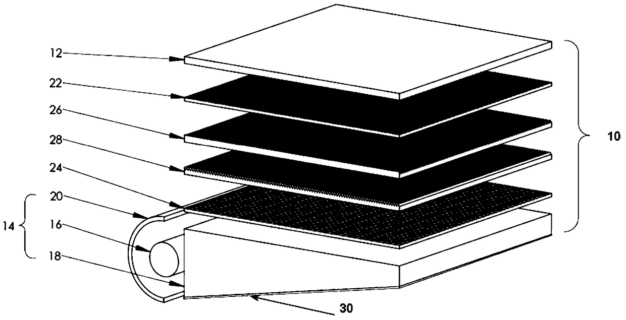
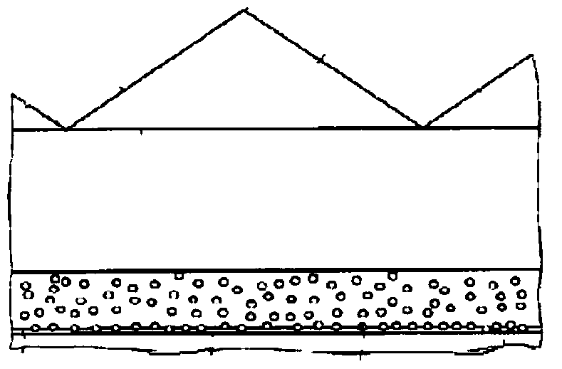
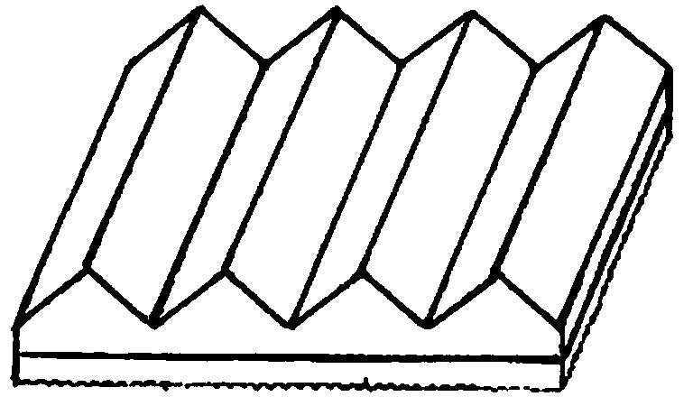
[0070] The invention relates to a diffusion prism substrate with functions of light collimation and light diffusion. More particularly, the present invention is directed to optical substrates having structured surfaces that enhance brightness or brightness by collimating light and enhancing light diffusion. In one aspect of the invention, the optical substrate is in the form of an optical substrate...


PUM

PropertyMeasurementUnit
angleaaaaaaaaaa
heightaaaaaaaaaa
gain coefficientaaaaaaaaaa

Abstract

The invention discloses a method for forming a concave-convex structure on a substrate, a method for making a mold and a method for forming an optical film, wherein the method for forming a concave-convex structure on a substrate is: using a control system A hard tool pierces a mold to sequentially carve a plurality of grooves on a surface of the mold, wherein the method of scoring the plurality of grooves is: maintaining the hard tool along a first direction upward a first line to score a first groove along the first direction; and maintaining the hard tool along a second line to score a second groove along the first direction, wherein by The increase in lateral width of the second groove controlled by the penetration depth of the hard tool is sufficient to intercept the first groove in a lateral direction of the second groove such that the first groove is separated by the second groove forming a plurality of grooves; and using the surface of the mold to imprint a thin film on the substrate to form the concave-convex structure on the substrate.

Description

technical field [0001] The present invention relates to optical substrates with structured surfaces, in particular to optical substrates for brightness enhancement and diffusion, and more particularly to brightness enhancement and diffusion substrates for use in flat panel displays with planar light sources. Background technique [0002] Flat panel display technology is generally used in television monitors, computer monitors and portable electronic displays (such as mobile phones, personal digital assistants (PDAs), digital cameras, digital tablets, etc.). A liquid crystal display (LCD) is a flat panel display that displays liquid crystal (LC) modules with an array of pixels to image images. [0003] figure 1 An example of an LCD display is shown. The backlit LCD 10 includes a liquid crystal (LC) display module 12 , a planar light source in the form of a backlight module 14 , and a number of optical films sandwiched between the LC module 12 and the backlight module 14 . ...

Claims


Application Information

Patent Timeline
Patent Type & Authority Patents(China)
IPC IPC(8): G02B5/02G02B5/04G02B3/00G02F1/13357B29C59/02
CPCB29C59/022B29L2011/00B29L2011/0016G02B3/0031G02B5/045G02F1/133606G02F1/133607
Inventor 杨景安邱威泰潘汉聪
Owner UBRIGHT OPTRONICS CORP
Why Eureka
Try Eureka