
A hanging type small target detection sonar system and detection method

A detection method and small target technology, applied in radio wave measurement systems, measurement devices, sound wave re-radiation, etc., can solve problems such as fixing on ships, shore bases or underwater, high manufacturing and construction costs, and difficulty in flexible deployment. , to achieve the effect of light weight, simple detection method and small volume

Active Publication Date: 2018-04-27
HARBIN ENG UNIV
View PDF3 Cites 0 Cited by
  • Summary
  • Abstract
  • Description
  • Claims
  • Application Information

AI Technical Summary

Problems solved by technology

On the one hand, the traditional sonar field is mainly aimed at the detection of large-scale surface and underwater targets, and the detection frequency is low, usually fixed on ships, shore-based or underwater, etc.; on the other hand, the existing small target detection sonar often uses high-resolution High-rate image sonar or hydrophone base array deployed on the bottom of the water for over-the-top detection, etc., but usually large in size, not easy to deploy flexibly, manufacturing and construction costs are relatively high, and sometimes it is difficult to move once deployed

Method used


Image

  • A hanging type small target detection sonar system and detection method
  • A hanging type small target detection sonar system and detection method
  • A hanging type small target detection sonar system and detection method

Examples


Embodiment approach 1

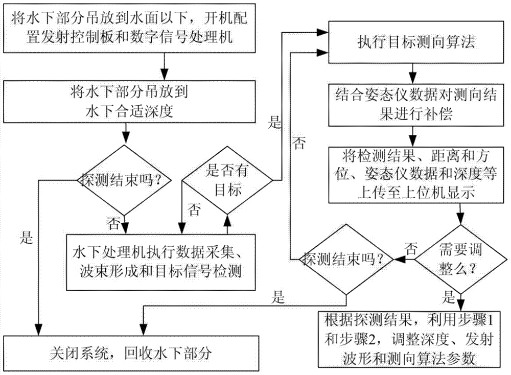
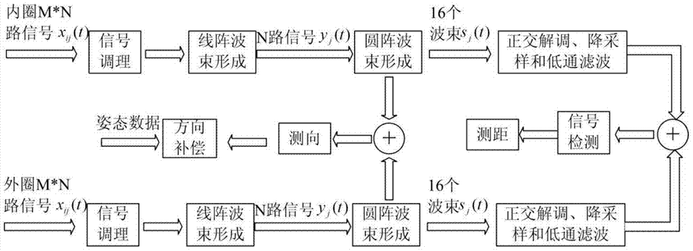
[0040] combined with figure 2 and image 3 , the implementation scheme 1 of target detection is as follows:

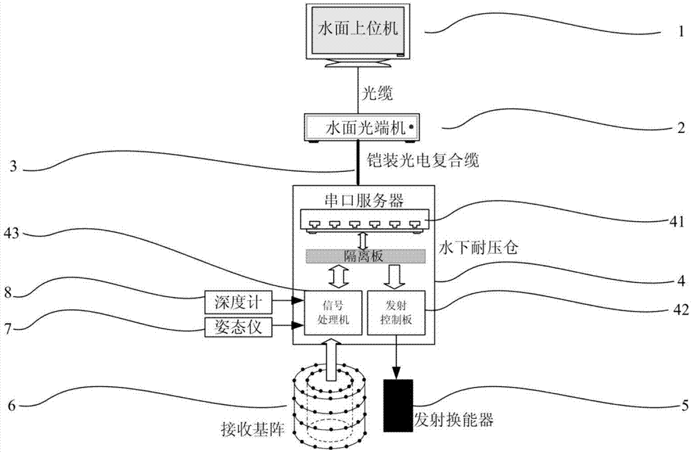
[0041] Step 1: Lift the underwater part below the water surface through the winch, start the system, configure the launch waveform parameters through the host computer, and send the parameters to the launch control board of the pressure chamber to launch the required waveforms, such as CW pulses, The pulse width is 100ms, the frequency is 14.3kHz, and the transmission period is 1.5s, so as to detect targets within 2000m. The host computer sends the configured relevant parameters to the underwater digital signal processor.

[0042]Step 2: Use the depth gauge and display control to control the underwater part to be hoisted to the required depth underwater, for example, 20m.

[0043] Step 3: The digital signal processor collects the signal output by the array, and executes beamforming and signal detection algorithms;

[0044] First, the output of each array element o...

Embodiment approach 2

[0076] Embodiment 2: The difference between this embodiment and the above target detection embodiment 1 is that: first, the passive detection method is adopted, and the active pulse signal does not need to be transmitted in step 2, but the noise signal radiated by the target is used for detection. Only the orientation information of the target can be obtained, so what is displayed on the host computer is the target orientation history curve. The two detection methods can be switched through the display and control of the host computer; the second detection algorithm is similar to the CW pulse detection method, the difference is that in step A, no quadrature demodulation is required, and down-sampling and low-pass filtering are directly performed. The third is that due to the low sound level of small target radiation noise, the detection distance of passive detection is much lower than that of active detection, but passive detection has the advantage of good concealment, so the ...


PUM


Abstract

The invention provides a dipping small-object detecting sonar system and a detecting method thereof. The dipping small-object detecting sonar system is composed of an underwater part and an on-water part, wherein connection and dipping between the underwater part and the on-water part are realized through an armored photoelectric composite cable. The underwater part comprises a transmission energy transducer, a double-layer cylindrical receiving array, an underwater signal processor and a serial server. The on-water part is a display console and performs data exchange with the underwater part through a water-surface optical terminal. After related parameters of the underwater signal processor and a transmission control panel are configured through the upper display console, the underwater part is dipped to an appropriate depth. The signal processor processes data which are output from the receiving array; the signal processor performs operations of wave beam formation, target detection, target positioning, etc.; and furthermore the signal processor uploads data of detection result, array gesture, depth, etc. to the upper display console for real-time displaying, thereby realizing 360-degree panoramic detection. The dipping small-object detecting sonar system and the detecting method thereof are used for various operation platforms and have advantages of low cost, small size, small weight, flexible configuration and high detecting performance.

Description

technical field [0001] The invention relates to a sonar system suitable for small target detection. The present invention also relates to a small target detection method. Background technique [0002] With the continuous development of my country's marine resources, various operating platforms appear on the sea to carry out investigations, research, exploration and exploitation of marine environment and resources, such as oil drilling platforms, various scientific research ships, and remote islands and reefs. Facing the threats of various small targets, there is an urgent need for a small target detection sonar with low cost, flexible deployment and good detection performance. [0003] Sonar is currently the most effective means of long-distance detection of underwater targets. Due to the characteristics of relatively small scale, strong maneuverability, and high concealment, small targets are difficult to detect, which is an important technical problem that needs to be sol...

Claims


Application Information

Patent Timeline
Patent Type & Authority Patents(China)
IPC IPC(8): G01S15/89
CPCG01S15/89
Inventor 聂东虎乔钢刘凇佐孙宗鑫周锋刘秉昊青昕马帅张义
Owner HARBIN ENG UNIV
Learn More