
device for transmitting torque

A technology for transmitting torque and axis of rotation, applied in springs/shock absorbers, clutches, vibration suppression adjustment, etc., can solve problems such as auditory interference, affecting the traction or driving performance of motor vehicles, and achieve the effect of good travel

Active Publication Date: 2019-08-16
SCHAEFFLER TECH AG & CO KG
View PDF5 Cites 0 Cited by
  • Summary
  • Abstract
  • Description
  • Claims
  • Application Information

AI Technical Summary

Problems solved by technology

The inhomogeneity can affect the traction or ride performance of the motor vehicle or can cause auditory disturbance

Method used


Image

  • device for transmitting torque
  • device for transmitting torque

Examples


Embodiment Construction

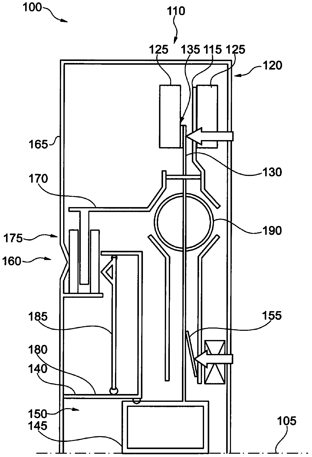
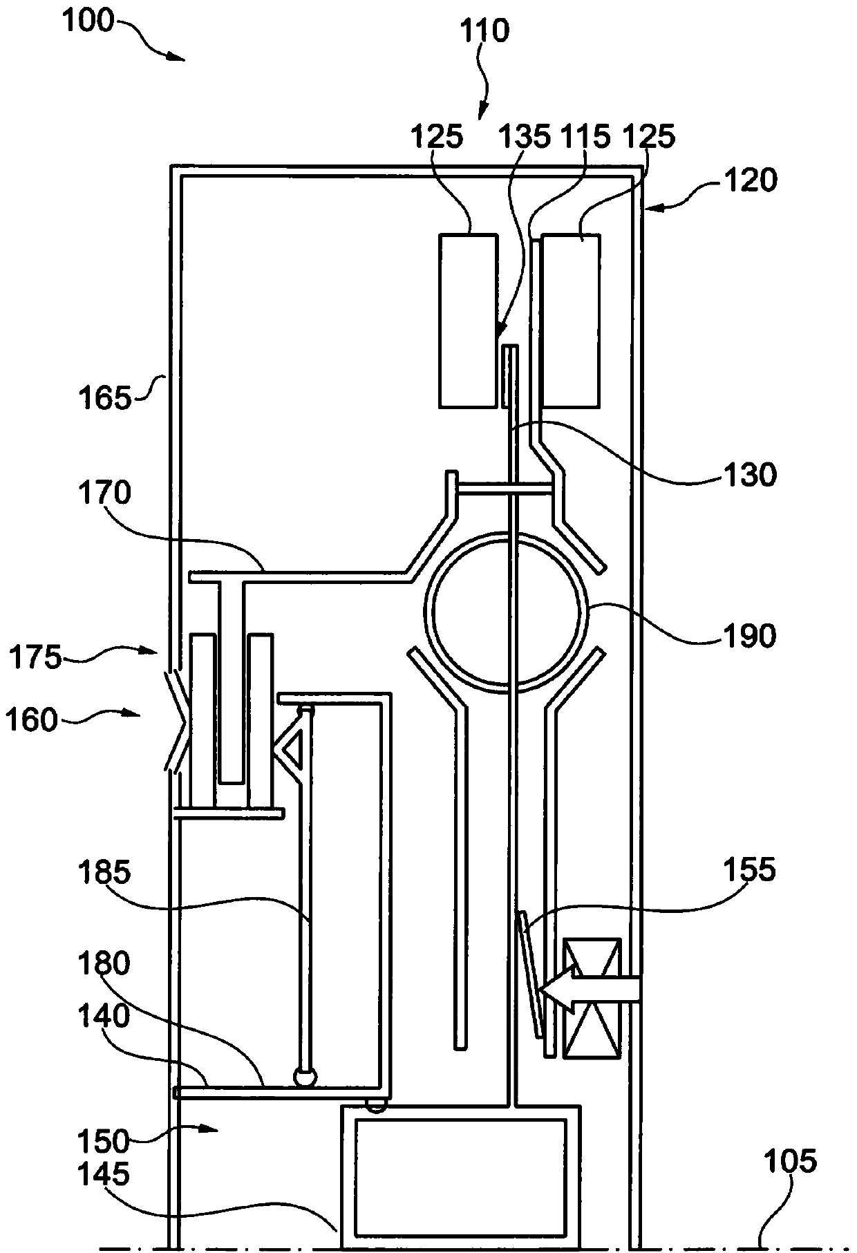
[0017] figure 1 A schematic illustration of a device 100 for transmitting torque about an axis of rotation 105 is shown. The device 100 includes a centrifugal pendulum 110 with a pendulum flange 115 and a pendulum mass 120 . The pendulum mass 120 can comprise two pendulum elements 125 which are arranged on different axial sides of the pendulum flange 115 and are connected to each other. Pendulum mass 120 is displaceable on a pendulum rail in a plane of rotation about axis of rotation 105 relative to pendulum flange 115 . In addition, a braking element 130 is provided, which can be pressed axially against the pendulum mass 120 or against one of the pendulum elements 125 in order to limit or prevent the relative movement of the pendulum mass 120 . The mobility of the pendulum flange 115 . The braking element 130 is preferably connected to the pendulum flange 115 in a rotationally fixed manner. A friction element 135 can be arranged between the braking element 130 and the pen...


PUM


Abstract

A device for transmitting torque, including a centrifugal pendulum having a pendulum flange and a pendulum mass, the pendulum flange being supported to rotate about the axis of rotation, the pendulum mass being mounted on the pendulum in a manner to be movable in the plane of rotation The flange also includes a braking element, which can be pressed toward the pendulum mass in the axial direction for braking the pendulum mass.

Description

technical field [0001] The invention relates to a device for transmitting torque, in particular in a drive train of a motor vehicle. Background technique [0002] A drive train is provided in a motor vehicle for connecting the drive motor to the drive wheels. Rotational motion is transmitted through the drive train, which may experience inhomogeneities, for example due to the configuration of the drive motor or due to uneven terrain. This inhomogeneity can affect the traction or driving behavior of the motor vehicle or can cause acoustic disturbances. Therefore, various measures are usually taken to isolate, eliminate or reduce this inhomogeneity. [0003] Measures for eliminating inhomogeneities in the transmitted rotational movement include a centrifugal pendulum with a pendulum flange and a pendulum mass mounted displaceably on the pendulum flange. The pendulum flange is arranged rotatably about an axis of rotation and follows the rotational movement of the drive train...

Claims


Application Information

Patent Timeline
Patent Type & Authority Patents(China)
IPC IPC(8): F16D43/08
CPCF16F15/145
Inventor M·屈恩勒S·马延沙因
Owner SCHAEFFLER TECH AG & CO KG
Learn More