
A kind of high-altitude grid installation method

An installation method and grid technology, which are applied to truss structures, joists, girders, etc., can solve the problems of low overall accuracy, complicated operation, and large engineering volume of high-altitude installation of grids. Stable installation and beautiful appearance

Active Publication Date: 2018-03-16
DUOWEI UNION GRP
View PDF6 Cites 0 Cited by
  • Summary
  • Abstract
  • Description
  • Claims
  • Application Information

AI Technical Summary

Problems solved by technology

[0005] The technical problem to be solved in this application is to provide a safe and efficient installation method for high-altitude grids, which solves the problems of low overall precision of conventional high-altitude installation grids, easy accumulation of deviations during the installation process, large engineering volume, and complicated operations

Method used


Image

  • A kind of high-altitude grid installation method
  • A kind of high-altitude grid installation method
  • A kind of high-altitude grid installation method

Examples


Embodiment

[0046] Example description

[0047] The high-altitude network frame installation method of the present application, by installing the initial starting span on the supporting base, using the supporting base and the two sides of the starting span as the basis for widening, four triangular edge grids are formed, and then the two opposite triangular The middle part of the edge grid is widened to form a new starting span, and then the installation is repeated on the basis of the new starting card until the installation of the high-altitude grid is completed, which realizes the safe and efficient installation of the high-altitude grid and avoids the installation of the conventional high-altitude grid Problems with complex operation and large engineering volume.

specific Embodiment

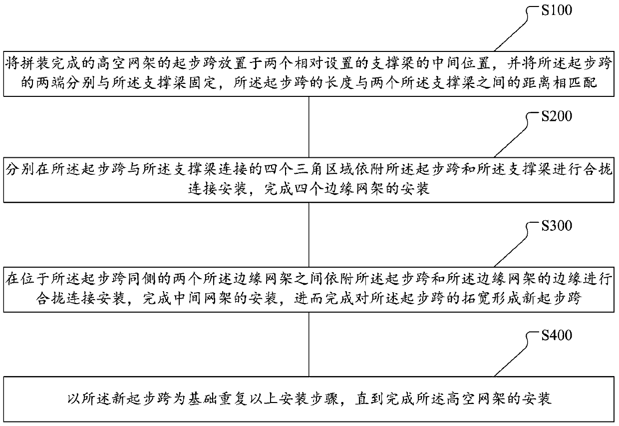
[0048] See attached figure 1 , is a schematic flow chart of the installation method of the high-altitude network frame of the present invention. The installation method of the high-altitude grid frame of the present invention comprises:

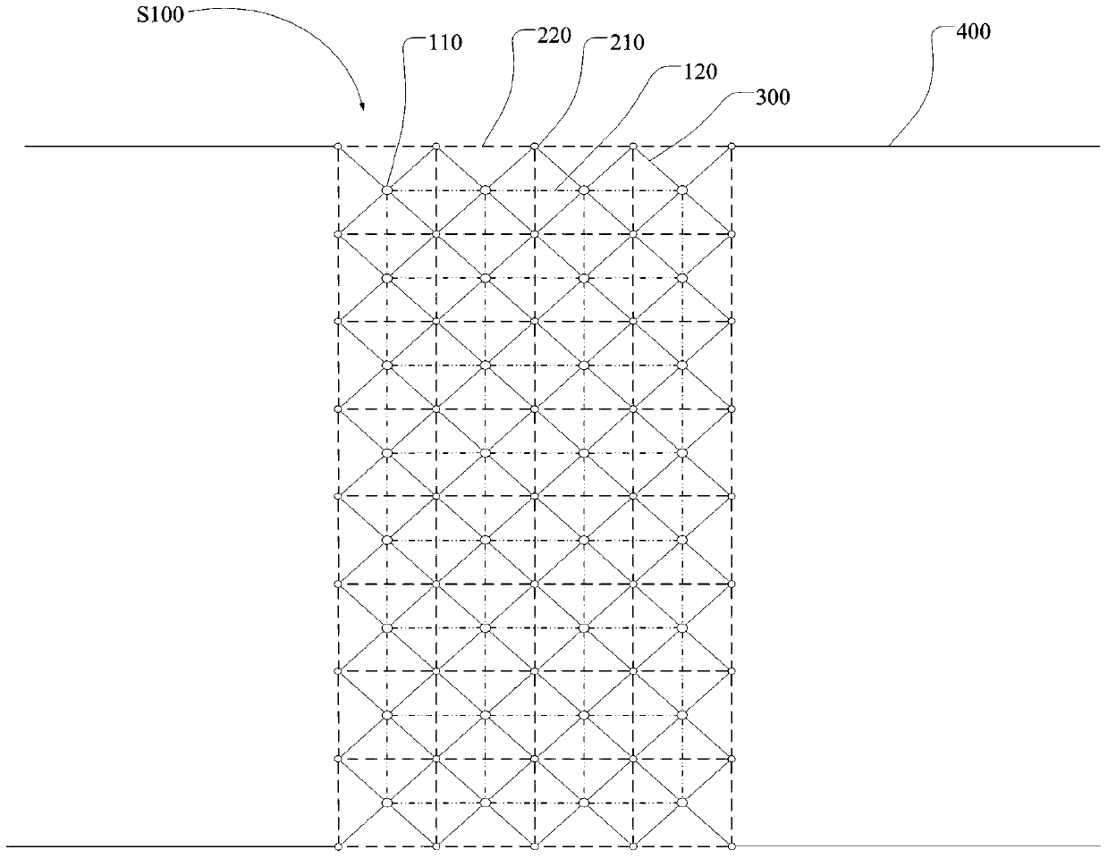
[0049] S100: Place the starting span of the assembled high-altitude network frame in the middle of four oppositely arranged supporting bases 400, and fix the two ends of the starting span to the supporting bases 400 respectively, the length of the starting span match the distance between the two support bases 400;

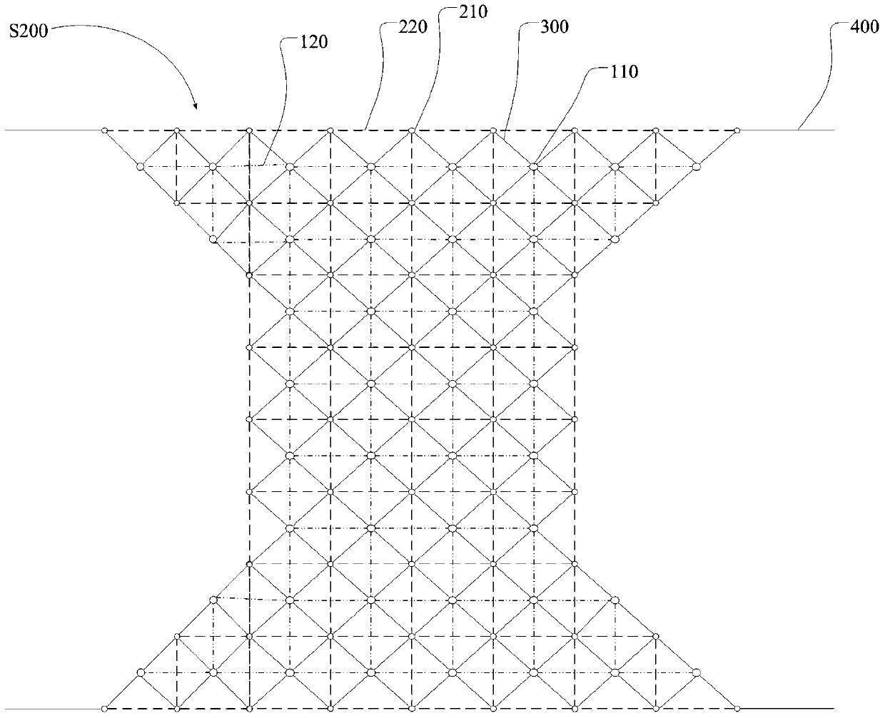
[0050] S200: Attach the starting span and the supporting base 400 to connect and install the four triangular areas where the starting span and the supporting base 400 are connected, and complete the installation of the four edge grids;

[0051] S300: Between the two edge grids located on the same side of the starting span, close and connect and install the edges of the starting span and the edge grids to complete the installatio...


PUM


Abstract

The invention relates to a high altitude grid structure mounting method. The high altitude grid structure mounting method comprises the following steps of placing a starting span of an assembled high altitude grid structure in middle positions of four oppositely arranged supporting bases; respectively fixing the two ends of the starting span together with the supporting bases; through depending on the starting span and the supporting bases, respectively performing closing and connecting mounting in four triangular areas, connected with the supporting base, of the starting span so as to finish the mounting of four edge grid structures; performing closing and connecting mounting between the two edge grid structures on the same side of the starting span so as to finish the mounting of a middle grid structure and then finish the expanding of the starting span to form a new starting span; and repeating the mounting steps on the basis of the new starting span until the high altitude grid structure is mounted. According to the invention, the grid structure is gradually expanded and mounted in a progressive way so that the high altitude grid structure is safely and efficiently mounted; and problems that the mounting operation of the traditional high altitude grid structure is complicated and the engineering quantity of the traditional high altitude grid structure is huge are solved.

Description

technical field [0001] The application relates to a grid installation method on the roof of a large building, in particular to a high-altitude grid installation method. Background technique [0002] The grid structure is a grid-like high-order hyperstatically indeterminate structure composed of multiple rods according to certain rules. Since all members can participate in the work, they have good mechanical performance, and their rigidity and integrity are superior to ordinary plane structures, and can effectively bear various asymmetric loads, concentrated loads and dynamic loads. The grid structure is more convenient to manufacture and install. Both rods and joints can be produced in the factory, which minimizes the on-site workload and does not require complicated technology, which facilitates the finalized and industrialized construction of the grid. [0003] Conventional grid installation methods include: overall hoisting method; when the site permits, the grid can be...

Claims


Application Information

Patent Timeline
Patent Type & Authority Patents(China)
IPC IPC(8): E04G21/14E04C3/11
CPCE04C3/11E04G21/14
Inventor 王超
Owner DUOWEI UNION GRP
Learn More